
Pull rod installing layout method of airplane auxiliary power device

An aircraft auxiliary power and layout method technology, applied in special data processing applications, instruments, electrical digital data processing, etc., can solve the problems of no layout, optimization, etc., reduce vibration transmission, reduce structural weight, improve installation efficiency and The effect of installation quality

Active Publication Date: 2014-06-11
XIAN AIRCRAFT DESIGN INST OF AVIATION IND OF CHINA
View PDF3 Cites 0 Cited by
  • Summary
  • Abstract
  • Description
  • Claims
  • Application Information

AI Technical Summary

Problems solved by technology

At present, when installing APU at home and abroad, only the convenience of the layout of the tie rods is generally considered, and the layout optimization based on mechanical properties is not carried out.

Method used


Image

  • Pull rod installing layout method of airplane auxiliary power device
  • Pull rod installing layout method of airplane auxiliary power device
  • Pull rod installing layout method of airplane auxiliary power device

Examples


Embodiment Construction

[0022] Below by specific embodiment and in conjunction with accompanying drawing, the present invention will be further described:

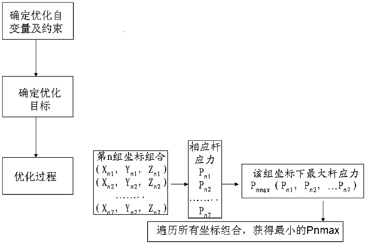
[0023] The layout method of the tie rods installed in the aircraft auxiliary power unit of the present invention utilizes engineering design software to carry out parametric modeling of the structure, and under the call of the optimization process control program, realizes the data transfer from the parametric entity structure to the finite element analysis software; in the finite element software Mesh the entity and apply conditions such as materials, constraints, and loads to the installation system, calculate the structural force or deformation of the bar system, and determine the optimal installation system by the optimization process based on the optimization goals such as system weight and manufacturability. Excellent structure.

[0024] Now take a certain type of aircraft auxiliary power unit (APU) installation system as an example to illu...


PUM


Abstract

The invention belongs to the installation technology of airplane airborne equipment and relates to an installing structure layout optimized method of an auxiliary power device. According to the pull rod installing layout method of the airplane auxiliary power device, engineering design software is utilized for structure parameterized modeling, and the data transfer from the parameterized entity structure to the finite element analysis software is realized under the invoking effect of flow process optimization control program; and in the finite element software, entities are subjected to meshing, in addition, the application of conditions of materials, restraining, loads and the like of an installing system is carried out, the structure stress or deformation of a rod system is calculated, and the optimum structure of the installing system is determined by an optimizing flow process according to optimizing targets such as the system weight, good manufacturability and the like. The method has the advantages that the installing structure with the minimum structure weight and the optimal stress form can be obtained, the structure weight is lightened, the vibration transfer is reduced, the installation efficiency and the installing quality are improved, and the layout optimization requirement of the installing system of the airplane auxiliary power device is met.

Description

technical field [0001] The invention belongs to the installation technology of aircraft airborne equipment, and relates to a method for optimizing the layout of an auxiliary power unit installation structure. Background technique [0002] One of the main difficulties in the design of the engine mounting system is the layout and structure optimization of the mounting system. At present, the design of the engine mounting system basically does not carry out the optimization of the component (or rod system) configuration and space layout, which makes the designed system components heavy and occupy a large volume. With the advancement of design technology, optimization design methods are generally used in aircraft structure design at home and abroad, which not only reduces the difficulty and risk of the installation system design, but also ensures the optimal design index of the installation system, making the system components lightweight and reducing the research cost. At pres...

Claims


Application Information

Patent Timeline
Patent Type & Authority Patents(China)
IPC IPC(8): G06F17/50
CPCY02T90/00
Inventor 屈展何晓静奚振吕奇峰
Owner XIAN AIRCRAFT DESIGN INST OF AVIATION IND OF CHINA
Learn More