Power grid scheduling cloud system

A power grid dispatching and cloud system technology, applied in transmission systems, electrical components, instruments, etc., to achieve high fault tolerance and cost-effective effects

Active Publication Date: 2012-10-24
CHINA ELECTRIC POWER RES INST +1
View PDF2 Cites 34 Cited by
  • Summary
  • Abstract
  • Description
  • Claims
  • Application Information

AI Technical Summary

Problems solved by technology

[0006] This technology can meet the needs of dispatching at the current stage and in the future, but in the long run, there are still deficiencies in the following aspects: in-depth support for collaborative work methods; cost improvement for equipment utilization, avoiding redundant construction, and unified maintenance requirements; system rapid scalability requirements; higher-level reliability requirements; higher-level efficiency requirements; further requirements in search, data, models, calculations, scheduling plans, etc.

Method used


Image

  • Power grid scheduling cloud system
  • Power grid scheduling cloud system
  • Power grid scheduling cloud system

Examples


Embodiment Construction

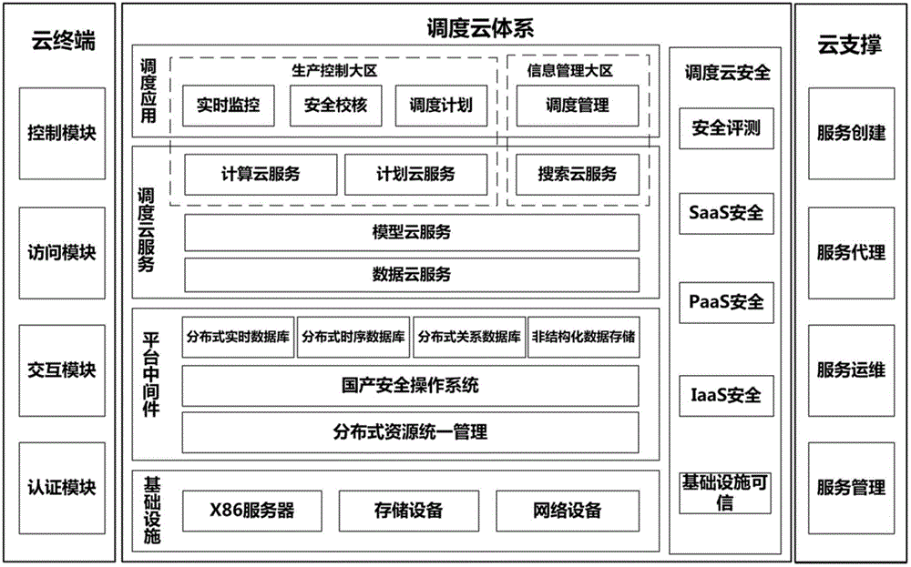
[0040]The present invention utilizes the new computing mode, business mode and application mode of cloud computing to redesign the dispatching system of the entire power grid as a whole.

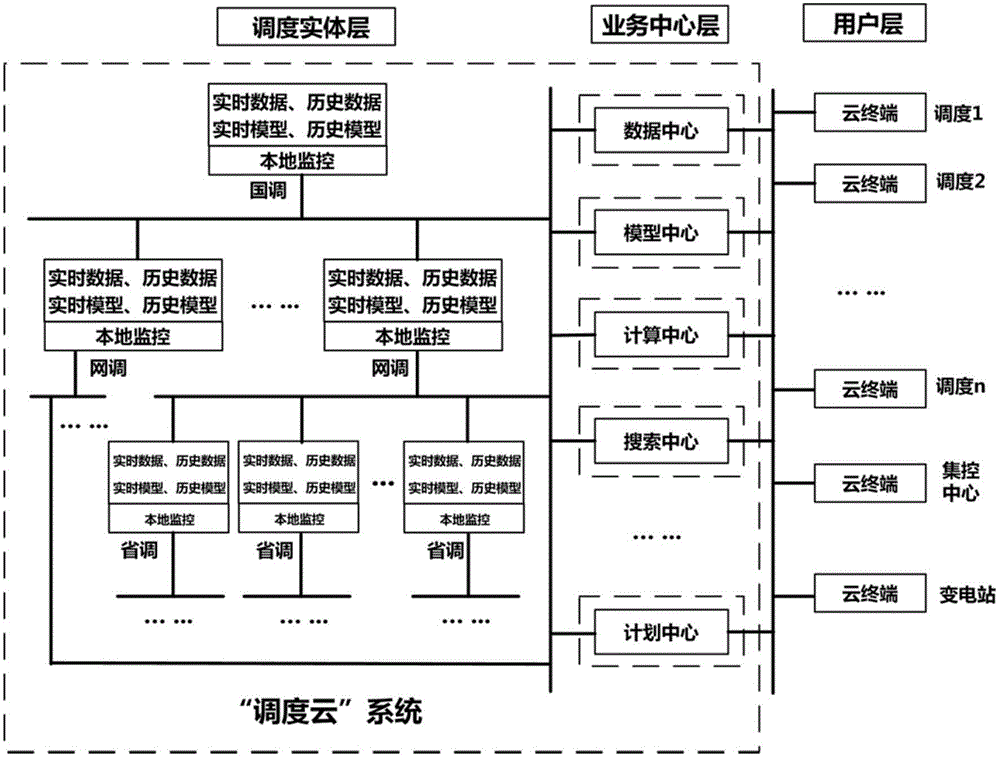
[0041] 1. Wide-area "scheduling cloud" architecture

[0042] It is the power grid dispatching cloud system, which is divided into three levels: dispatching entity layer, business center layer and dispatching application layer. figure 1 shown.

[0043] 1) Scheduling entity layer

[0044] The dispatching entity layer mainly includes various dispatching infrastructures—that is, various actual physical devices. In the present invention, the scheduling entity layer is geographically distributed.

[0045] The actual physical equipment is scattered in all levels of scheduling (including national, network, provincial and other levels), but not only local data and applications are stored on it, but also some data in other scheduling areas can be saved, so that Scheduling massive data has a certai...


PUM


Abstract

The invention provides a power grid scheduling cloud system. The power grid scheduling cloud system comprises a scheduling physical layer, a service center layer and a user layer which are sequentially arranged. According to the power grid scheduling cloud system, a new calculating mode of cloud computing, a business mode and an application mode are adopted, and the scheduling system of the whole power grid is integrally designed again.

Description

technical field [0001] The invention belongs to the field of electric power systems and automation thereof, and in particular relates to a power grid dispatching cloud system. Background technique [0002] The dispatching automation system is the core and soul of the entire power automation system. The background technologies involved in the present invention mainly include: smart grid dispatching technology support system, cloud computing technology, virtualization technology, parallel technology, and desktop cloud technology. [0003] 1. Scheduling technical support system technology [0004] Adopting the system structure following the service-oriented (SOA) concept, a unified scheduling and hierarchical management mode has been formed. Its specific components include: dispatching technical support system platform, dispatching real-time monitoring and control applications, dispatching planning applications, dispatching management applications, and safety checking applicat...

Claims


Application Information

Patent Timeline
Patent Type & Authority Applications(China)
IPC IPC(8): G06Q10/06G06Q50/06H04L29/08
Inventor 姚建国杨胜春曹阳高志远
Owner CHINA ELECTRIC POWER RES INST
Why Eureka
Try Eureka