Fractal yagi printed antenna of coplanar waveguide feed

A technology of coplanar waveguide and printed antenna, applied in the field of fractal Yagi printed antenna, can solve the problems of bulky antenna, unfavorable miniaturization, mass production, and complexity, and achieve compact feeding form, favorable miniaturization, and high gain Effect

Inactive Publication Date: 2012-10-24
HARBIN INST OF TECH
View PDF3 Cites 6 Cited by
  • Summary
  • Abstract
  • Description
  • Claims
  • Application Information

AI Technical Summary

Problems solved by technology

[0003] In order to solve the problem that the existing directional antenna is relatively large and complicated, which is not conducive to miniaturization and mass production, and the integration with the communication circuit, the present invention further proposes a fractal Yagi printed antenna fed by a coplanar waveguide

Method used


Image

  • Fractal yagi printed antenna of coplanar waveguide feed
  • Fractal yagi printed antenna of coplanar waveguide feed
  • Fractal yagi printed antenna of coplanar waveguide feed

Examples


specific Embodiment approach 1

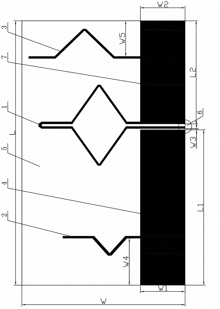
[0007] Specific implementation mode one: combine figure 1 Describe this embodiment mode. A coplanar waveguide-fed fractal Yagi printed antenna described in this embodiment mode includes an active vibrator 1, a director 2, a reflector 3, a first printed metal floor 4, a dielectric board 5, a common The surface waveguide feed port 6 and the second printed metal floor 7, the first printed metal floor 4, and the second printed metal floor 7 are arranged in the lower part of one side surface of the dielectric board 5 in a straight line, and the director 2, The active vibrator 1 and the reflector 3 are installed on one side surface of the dielectric board 5 in sequence from left to right. The left arm and the right arm of the lower part of the active vibrator 1 are located on the first printed metal floor 4 and the second printed metal floor. Between the floors 7, and the left arm of the lower part of the active vibrator 1 is in contact with the lower edge of one side surface of the...

specific Embodiment approach 2

[0009] Specific implementation mode two: combination figure 1 To illustrate this embodiment, the length L of the dielectric board 5 of the coplanar waveguide-fed fractal Yagi printed antenna described in this embodiment is 170mm-175mm, and the width W of the dielectric board 5 is 85mm-90mm. Other components and connections are the same as those in the first embodiment.

specific Embodiment approach 3

[0010] Specific implementation mode three: combination figure 1 Describe this embodiment, the length L1 of the first printed metal floor 4 of the fractal Yagi printed antenna described in this embodiment is 100mm-105mm, and the width W1 of the first printed metal floor 4 is 30mm -35mm, the length L2 of the second printed metal floor 7 is 60mm-65mm, and the width W2 of the second printed metal floor 7 is the same as the width W1 of the first printed metal floor 4 . Other components and connections are the same as those in the first embodiment.


PUM


Abstract

The invention relates to a fractal yagi printed antenna of coplanar waveguide feed, which relates to a yagi printed antenna, and in particular to a fractal yagi printed antenna of coplanar waveguide feed. The invention aims at solving at solving the problems of the miniaturization and mass production of the antenna and the integration of a communication circuit caused by the large and complicated size of a guide antenna. The fractal yagi printed antenna is characterized in that a first printed metal floor board and a second printed metal floor board are arranged on the lower part of one side surface of a medium plate in a linear way, a guide device, an active vibrator and a reflector are sequentially installed on one side surface of the medium plate from left to right, both a left arm and a right arm on the lower part of the active vibrator are arranged between the first printed metal floor board and the second printed metal floor board, the lower part of the guide device is connected with the first printed metal floor board into a whole, the lower part of the reflector is connected with the second printed metal floor board into a whole, and a coplanar waveguide feed port is arranged between the first printed metal floor board and the second printed metal floor board. The fractal yagi printed antenna is used for the technical field of radio.

Description

technical field [0001] The invention relates to a Yagi printed antenna, in particular to a fractal Yagi printed antenna fed by a coplanar waveguide. Background technique [0002] Directional antenna, also known as Yagi antenna or Yagi-Uda antenna, is a directional radiation antenna, usually composed of an active vibrator, one to two reflectors and several directors. The current induced on the reflector and the active vibrator work together to realize directional radiation. Since it was invented by Yagi Hideji and Uda Taro of Tohoku University in Japan in 1928, it has been widely used in the field of radio communication and radar. With the development of communication technology, there are many forms of this type of antenna, which are mainly divided into two categories: traditional metal cylindrical dipole type guide antenna and printed guide antenna. The traditional metal cylindrical vibrator type guide antenna is still widely used in television, radar and other fields. D...

Claims


Application Information

Patent Timeline
Patent Type & Authority Applications(China)
IPC IPC(8): H01Q19/30H01Q1/38H01Q1/48
Inventor 刘曦林澍马欣茹田雨陆加王力卓王立娜
Owner HARBIN INST OF TECH
Why Eureka
Try Eureka