Overvoltage protection circuit, power module and overvoltage protection method

A technology for protecting circuits and power modules, which is used in protection against overvoltage, emergency protection circuit devices, electrical components, etc. It can solve the problem of main power shutdown, protection circuit malfunction, and large difference in OVP overvoltage checkpoints of power supply boards. and other problems, to achieve the effect of accurate setting value, reducing difficulty, and overcoming the malfunction of the protection circuit

Active Publication Date: 2015-09-30
TPV DISPLAY TECH (XIAMEN) CO LTD
View PDF3 Cites 0 Cited by
  • Summary
  • Abstract
  • Description
  • Claims
  • Application Information

AI Technical Summary

Problems solved by technology

[0009] (1) The upper and lower limits of the zener diode ZD2 and ZD3 have a large difference in the voltage regulation value, which will cause a large difference in the OVP overvoltage checkpoint of different power boards
[0010] (2) Zener diodes ZD2 and ZD3 still have leakage current Ir before they are not turned on. When their body temperature rises, the leakage current will increase. In a wet environment, it is easy to cause the malfunction of the Q5 NPN transistor due to the increase of the leakage current of ZD2 and ZD3, and finally lead to the malfunction of the entire overvoltage protection circuit and turn off the main power supply
[0011] (3) During normal operation, the negative terminal voltage of D4 is greater than the positive terminal voltage, which makes the D4 diode reverse cut-off, but the diode usually has a large Ir Reverse leakage current, when in high temperature and high humidity environment, the reverse leakage current of the diode increases. If the resistance value of R12 is set too large at this time, due to the problem of reverse leakage current of D4, there will be a gap between the two ends of the R12 resistor. The voltage difference △V=R12*Ir, when the voltage difference is large, the PNP transistor Q4 starts to conduct, and the Q4 conduction generates a current in the emitter electrode and the collector emitter to make the transistor Q5 conduct, and finally both Q4 and Q5 are in the Saturation conduction state, when the protection circuit malfunctions
[0012] Due to the above problems in this circuit, it is difficult for an engineer with little experience to make a very correct selection of all electronic components in the circuit. If some component parameters are slightly set It is not very appropriate. For example, if the resistance value of resistor R9 / R12 is set too high, it is easy to cause the malfunction of the overvoltage protection circuit under high temperature and high humidity conditions. Therefore, it is necessary to provide a solution for the above problems

Method used


Image

  • Overvoltage protection circuit, power module and overvoltage protection method
  • Overvoltage protection circuit, power module and overvoltage protection method
  • Overvoltage protection circuit, power module and overvoltage protection method

Examples


Embodiment Construction

[0033] In order to describe the technical content, structural features, achieved goals and effects of the present invention in detail, the following will be described in detail in conjunction with the embodiments and accompanying drawings.

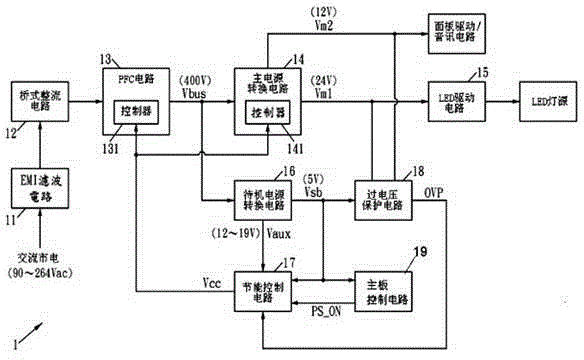
[0034] figure 1 It is a block diagram of a power supply module of an existing high-power liquid crystal display product. See figure 1 , the power module 1 includes an electromagnetic interference (Electro Magnetic Interference, EMI) filter circuit 11, a bridge rectifier circuit 12, a power factor correction (Power Factor Correction, PFC) circuit 13, a main power conversion circuit 14, a light-emitting diode (Light-Emitting Diode , LED) drive circuit 15 , standby power conversion circuit 16 , energy saving control circuit 17 and overvoltage protection circuit 18 . AC mains (such as 90-264Vac) passes through EMI filter circuit 11 to filter out conductive EMI noise, bridge rectifier circuit 12 for full-wave rectification, PFC circuit 13 to...


PUM


Abstract

The invention discloses an overvoltage protection circuit, a power module and an overvoltage protection method. The power module is applied to a liquid crystal display product, comprises the overvoltage protection circuit and also comprises an energy-saving control circuit; the overvoltage protection circuit comprises first main power supply voltage and second main power supply voltage; wherein the first main power supply voltage is used as power supply input end voltage of an LED (light-emitting diode) drive circuit of an LED lamp tube of a liquid crystal panel; the second main power supply voltage is used for providing required power source of an internal circuit to a liquid crystal display product; the overvoltage protection circuit is used for providing overvoltage protection to the first main power supply voltage and the second main power supply voltage, and the energy-saving control circuit is used for saving more energy and electricity for the liquid crystal display product under a standby mode.

Description

technical field [0001] The invention relates to a liquid crystal display and liquid crystal display products, in particular to an overvoltage protection circuit, a power supply module and an overvoltage protection method. Background technique [0002] figure 1 It is a block diagram of a power supply module of an existing high-power liquid crystal display product. See figure 1 , the power module 1 includes an electromagnetic interference (Electro Magnetic Interference, EMI) filter circuit 11, a bridge rectifier circuit 12, a power factor correction (Power Factor Correction, PFC) circuit 13, a main power conversion circuit 14, a light-emitting diode (Light-Emitting Diode , LED) drive circuit 15 , standby power conversion circuit 16 , energy saving control circuit 17 and overvoltage protection circuit 18 . AC mains (such as 90-264Vac) passes through EMI filter circuit 11 to filter out conductive EMI noise, bridge rectifier circuit 12 for full-wave rectification, PFC circuit ...

Claims


Application Information

Patent Timeline
IPC IPC(8): H02H3/20H02H7/10
Inventor 林家右
Owner TPV DISPLAY TECH (XIAMEN) CO LTD
Why Eureka
Try Eureka