Machine tool thermal displacement correction method and thermal displacement correction device

A thermal displacement and machine tool technology, applied in feeding devices, automatic control devices, computer control, etc., can solve problems such as thermal displacement errors

Inactive Publication Date: 2012-10-24
JTEKT CORP
View PDF5 Cites 4 Cited by
  • Summary
  • Abstract
  • Description
  • Claims
  • Application Information

AI Technical Summary

Problems solved by technology

However, in practice the columns are not inclined at a constant inclination angle, so thermal

Method used


Image

  • Machine tool thermal displacement correction method and thermal displacement correction device
  • Machine tool thermal displacement correction method and thermal displacement correction device
  • Machine tool thermal displacement correction method and thermal displacement correction device

Examples


no. 1 approach

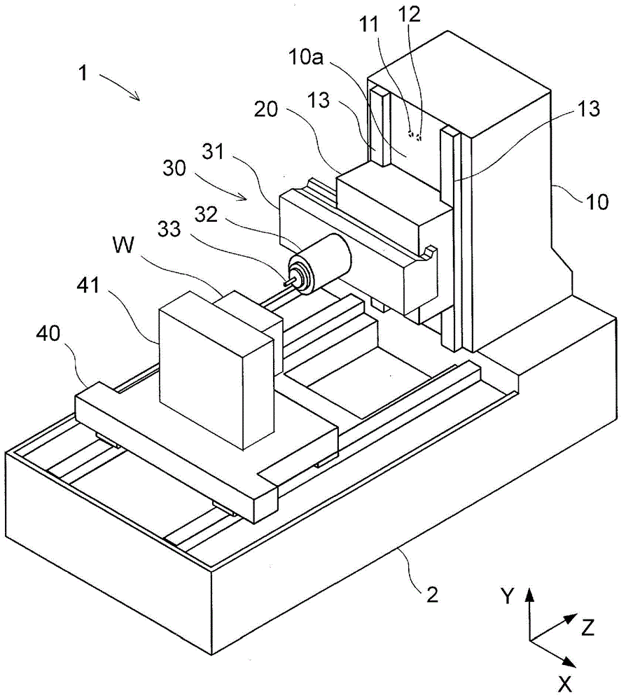
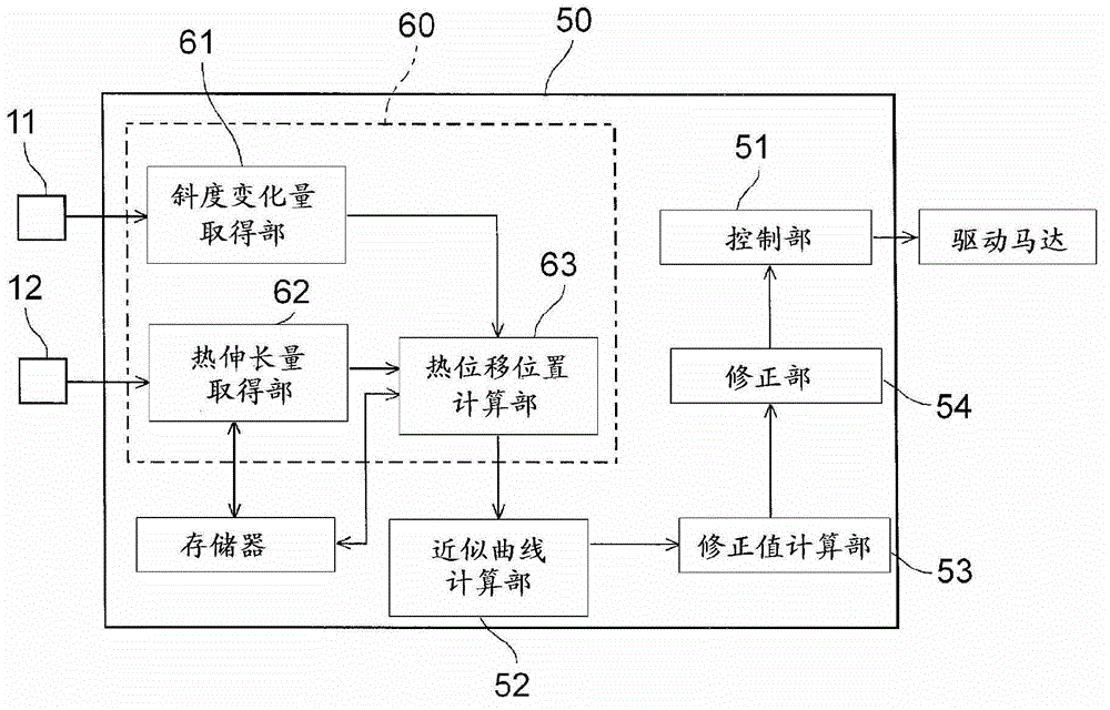
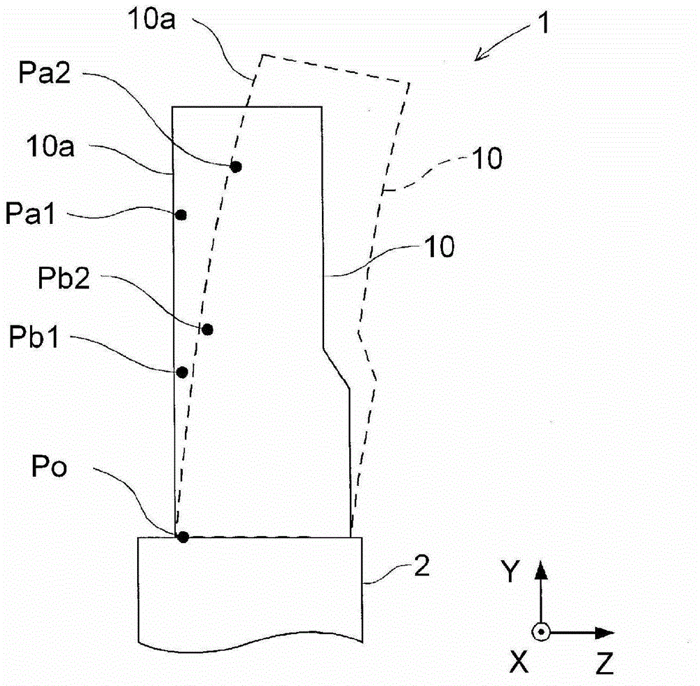
[0072] refer to Figure 1~Figure 3 The thermal displacement correction device of the machine tool 1 according to the first embodiment will be described. figure 1 is an overall view of the machine tool 1 . figure 2 is a block diagram showing a thermal displacement correction device. image 3 It is a side view showing the deformed state of the column.

[0073] (Structure of machine tool 1)

[0074] like figure 1 As shown, the machine tool 1 has: a base 2, a column 10 (equivalent to the "support" of the present invention), a saddle 20 (equivalent to the "moving body" of the present invention), a spindle base 30, a table 40, and a numerical control Device 50 (equivalent to the "thermal displacement correction device" of the present invention). A guide rail in the Z-axis direction (a direction parallel to the ground) is formed on the upper surface of the base 2, and the base 2 is placed on the ground. The workpiece W is a machined component machined by the machine tool 1 . ...

no. 2 approach

[0122] refer to Figure 6~Figure 8 The thermal displacement correction device of the machine tool 1 according to the second embodiment will be described. Image 6 is a block diagram showing the thermal displacement correction device 150 . Figure 7 It is an explanatory diagram of the calculation of the correction value. Figure 8 Yes Figure 7 A partial enlargement of the . Here, the calculation method of the thermal displacement position of each inspection point in the thermal displacement correction inspection point position information acquisition process of the second embodiment is different from that of the first embodiment. The rest of the structure is substantially the same as that of the first embodiment, so detailed description is omitted.

[0123] like Image 6 As shown, the inspection point position information acquisition unit 160 of the thermal displacement correction device 150 of this embodiment includes a thermal displacement post-slope acquisition unit 164 ...


PUM


Abstract

The invention provides a machine tool thermal displacement correction method and a thermal displacement correction device. Disclosed is a machine tool thermal displacement correction method comprising an inspection point information acquisition process (60) for acquiring thermal deformation positions in at least three inspection points which are set on a support body (10); an approximate curve calculating process (52) for calculating an approximate curve (C) of a deformed shape of the support body (10) on the basis of the thermal displacement positions at the inspection points; a correction value calculating process (53) for calculating a correction value (Rz) for a command position for a movable body (20) on the basis of said command position and the approximate curve (C); and a correction process (56) for correcting the command position for the movable body (20) by means of the correction value (Rz).

Description

technical field [0001] The invention relates to a thermal displacement correction method and a thermal displacement correction device of a machine tool. Background technique [0002] A machine tool processes a workpiece by controlling the position of each drive shaft with a control device. In the processing performed by the machine tool, the thermal influence of the machine tool may cause thermal deformation of the support body supporting the moving body. Since the thermal deformation of the support affects the position of the moving body, there is a possibility that processing accuracy may be reduced. Therefore, for example, Patent Document 1 discloses a method of measuring the inclination of a column using a distance sensor and correcting a command position of a drive shaft. [0003] Reference: Japanese Patent Laid-Open No. 2009-184077 [0004] In the conventional thermal displacement correction method, it is possible to measure the inclination angle in the case of incl...

Claims


Application Information

Patent Timeline
IPC IPC(8): B23Q15/18B23Q17/00G05B19/404
CPCG05B2219/49206B23Q11/0007G05B19/404B23Q15/18Y10T408/16
Inventor 大西主洋
Owner JTEKT CORP
Why Eureka
Try Eureka