Chilling unit

A refrigeration and refrigeration cycle technology, used in refrigerators, refrigeration components, refrigeration and liquefaction, etc.

Active Publication Date: 2012-10-24
TOSHIBA CARRIER CORP
View PDF11 Cites 11 Cited by
  • Summary
  • Abstract
  • Description
  • Claims
  • Application Information

AI Technical Summary

Problems solved by technology

[0004] In addition, in the refrigeration unit, not only the water circulation pump and water piping that guide water to the water heat exchanger, but also a control box that accommodates electronic componen

Method used


Image

  • Chilling unit
  • Chilling unit
  • Chilling unit

Examples


Embodiment Construction

[0021] Embodiments of the present invention will be described below based on the drawings.

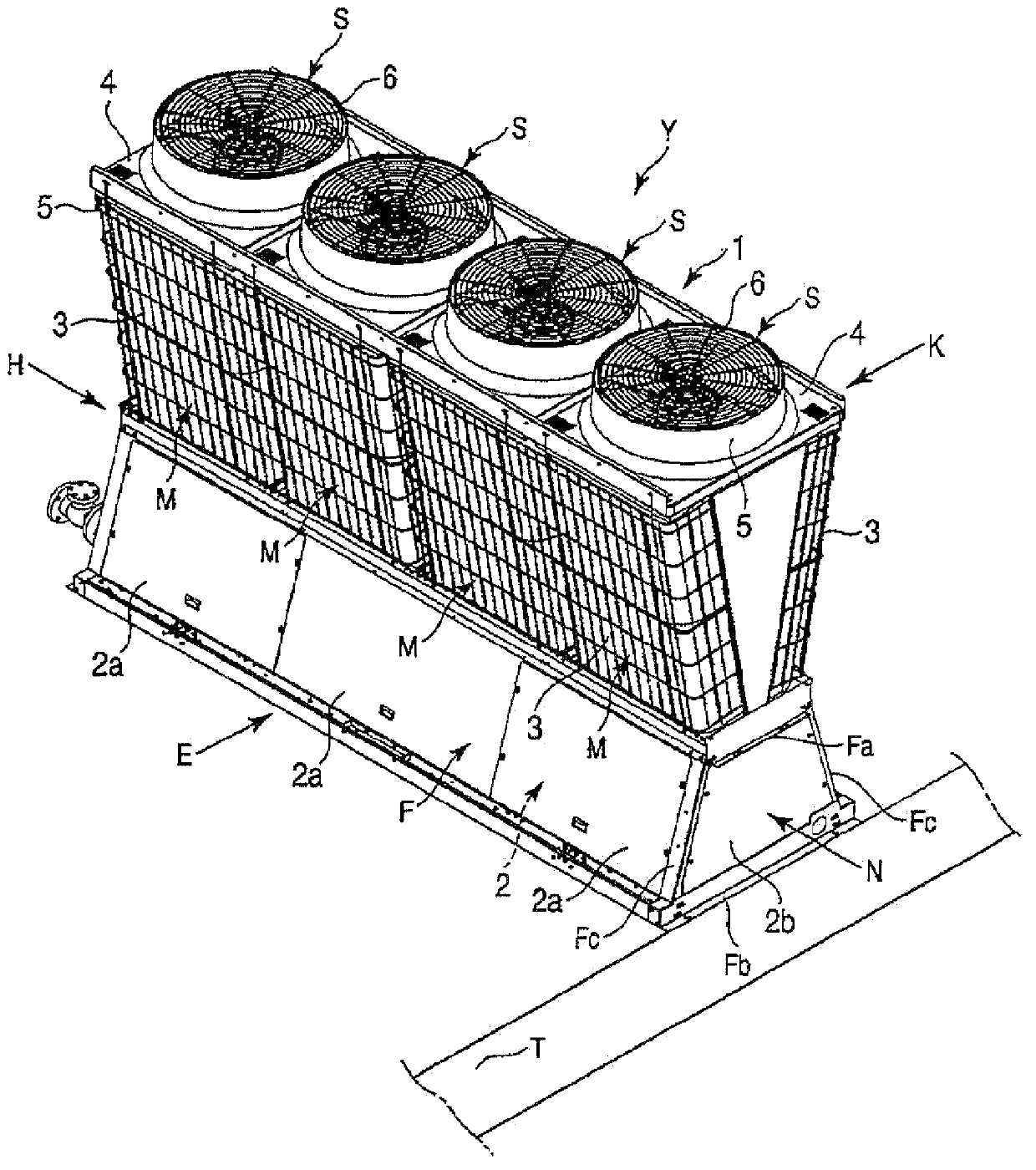
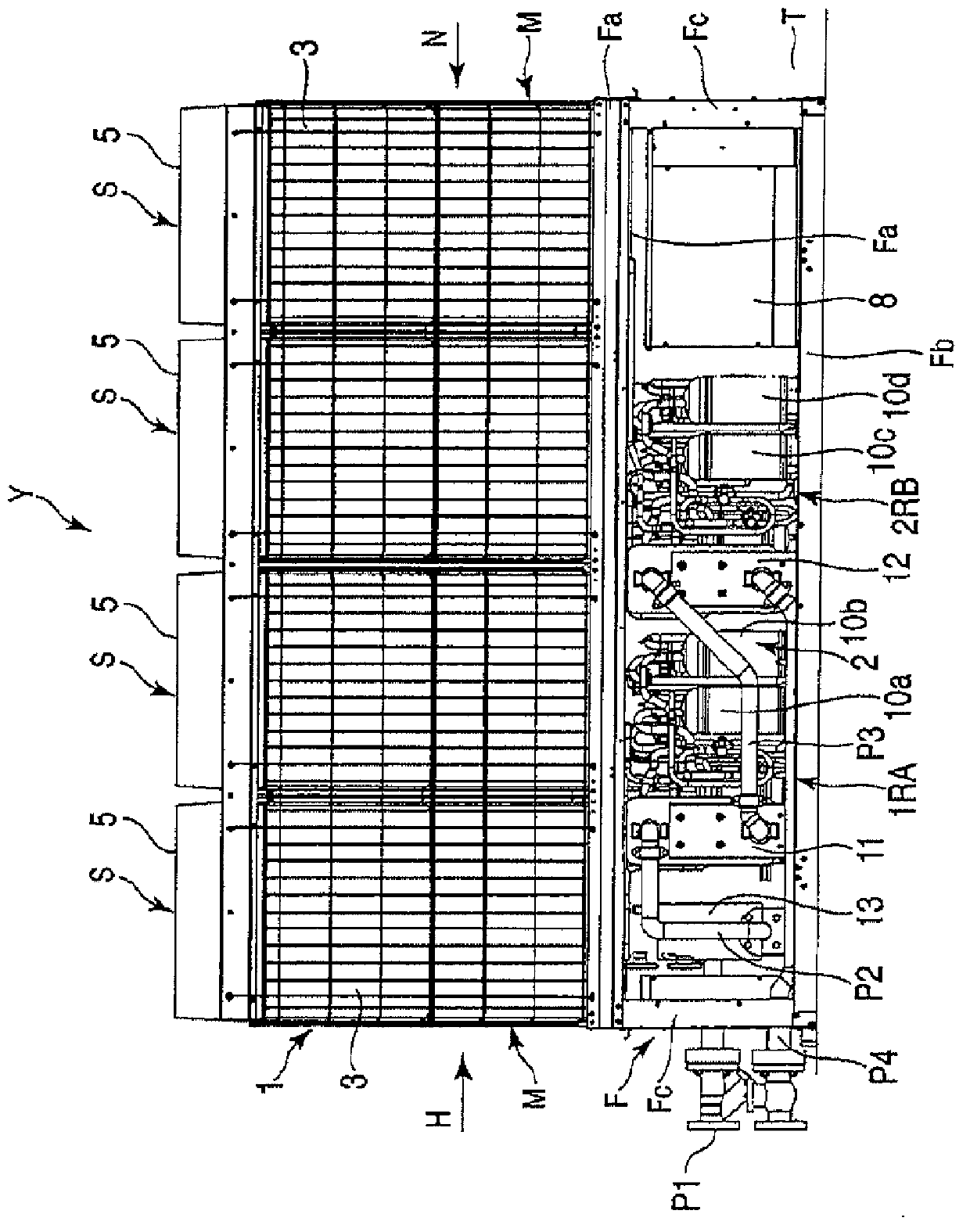
[0022] figure 1 is a perspective view of the fully assembled refrigeration unit Y, figure 2 It is a side view of the refrigeration unit Y in a state in which a side panel 2 a of a machine room 2 described later is removed.

[0023] The above-mentioned refrigerating unit Y generates cold water or warm water, for example, uses the obtained cold water to cool the air to cool the room (indoor), or uses the obtained warm water to heat the air to play a indoor (indoor) cooling effect. thermal effect. In addition to air conditioning units, it can also be used as a heat pump water heater.

[0024] Here, the refrigerating unit Y has a rectangular shape formed by mutually parallel long-side directions and short-side directions in plan view. In addition, a passage T through which the operator can pass is formed along one short side direction, and it will be inconvenient for the operator to p...


PUM


Abstract

Disclosed is a chilling unit comprised of a housing (F) wherein a heat exchange unit (1) provided with an air heat exchanger (3) is mounted on the top of the housing, and a machine chamber (2) is formed on the inside of the housing; a plurality of independent refrigeration cycle units (1RA), (2RB) which are contained in the machine chamber (2), and are comprised of refrigeration cycle devices excluding the air heat exchanger (3); and a control box (8) provided with a water circulation pump (13) and electronic components for controlling. The water circulation pump (13), the first refrigeration cycle unit (1RA), the second refrigeration cycle unit (2RB), and the control box (8) are arranged in this order from the back side to the front side of the housing (F), so that the control box (8) which contains electronic components that receive various kinds of signals to control electric components, can be located at the most appropriate position. Thus, the maintenance operation for the control box (8) can be easily performed, and the operability can be improved.

Description

technical field [0001] The present invention relates to a refrigeration unit constituting an air conditioner, a heat pump water heater, etc. suitable for use in, for example, large-scale buildings. Background technique [0002] A heat exchange unit, a so-called refrigeration unit, is disclosed. The refrigeration unit (heat exchange unit) is composed of a heat exchange room, a machine room, an air heat exchanger arranged in the heat exchange room, a blower for blowing air to the air heat exchanger, and a refrigeration cycle housed in the machine room. Component configuration (for example, Japanese Patent Laid-Open No. 2007-163017). [0003] The air heat exchangers are disposed so as to face each other in a substantially V-shape when viewed from the front. The above-mentioned mechanical chamber is formed in a substantially inverted V shape when viewed from the front, and houses a compressor, a four-way valve, an expansion valve for expanding the refrigerant, a water heat exc...

Claims


Application Information

Patent Timeline
IPC IPC(8): F24F1/22F24F1/16F24F1/56F24F5/00F25B1/00
CPCF24F1/36F24F1/68F25B6/02F24F2013/207F25B39/04F25B2400/06F24F1/18F24F1/50F24F13/30F24F1/16F24F5/00F25B1/00
Inventor 室井邦雄丹野英树冈田成浩小泽光辅渡边裕昭松本宪二郎石黑孝光
Owner TOSHIBA CARRIER CORP
Why Eureka
Try Eureka