Curve cutting equipment

A cutting equipment and curve technology, applied in the field of curve cutting equipment, can solve the problems of poor product edge effect, inconvenient curve cutting, loud vibration machine noise, etc., and achieve the effects of low cost, low cutting energy consumption, and low equipment cost

Inactive Publication Date: 2012-10-31
XIAMEN ZHENGLIMING METALLURGICAL MACHINERY
View PDF5 Cites 10 Cited by
  • Summary
  • Abstract
  • Description
  • Claims
  • Application Information

AI Technical Summary

Problems solved by technology

This solution also has the following disadvantages: in order to ensure that the cutting knife cuts the object smoothly, it is necessary to ensure that the shape of the cutting knife matches the tangent line of each point of the curved cutting seam, and in essence, the tangent line of each point of the curved cutting seam is changing in real time. , so it is very inconvenient to use this cutting equipment for curve cutting, and there are often knife breaking accidents
Use the needle knife to move up and down to cut the object to be cut. Although this solution can solve the knife breaking accident, it also has the following disadvantages: 1. Because the needle vibration is used to achieve cutting, the edge effect of the cut product is not good, and there are sawtooth Phenomenon, not smooth enough, generally after cutting, manual trimming is required; 2. The knife seat needs to drive a vibrating machine and needle knife and other related devices, the weight is relatively large, and a second power part with greater power is required; 3. Vibrating machine noise relatively bigger

Method used


Image

  • Curve cutting equipment
  • Curve cutting equipment
  • Curve cutting equipment

Examples


Embodiment Construction

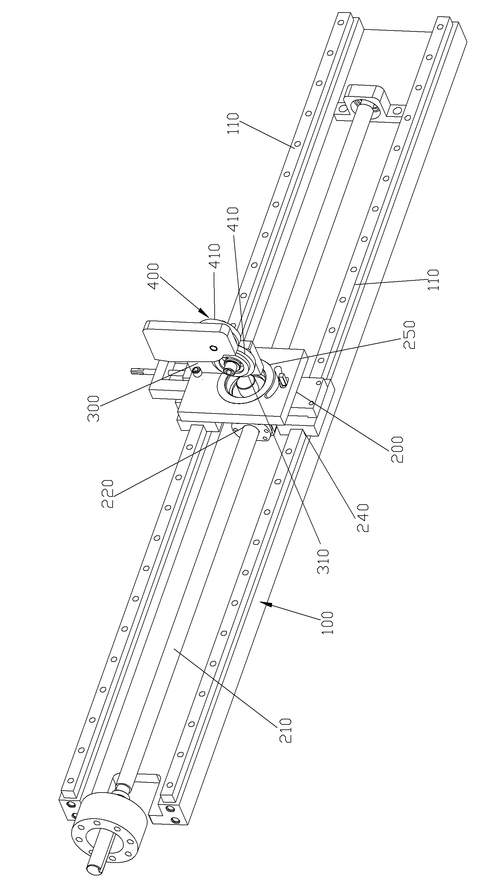
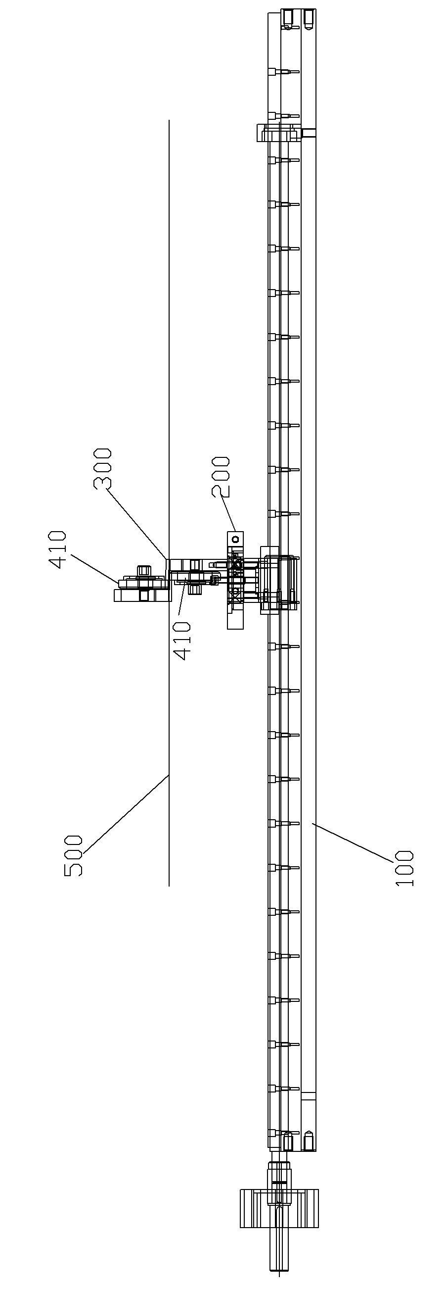
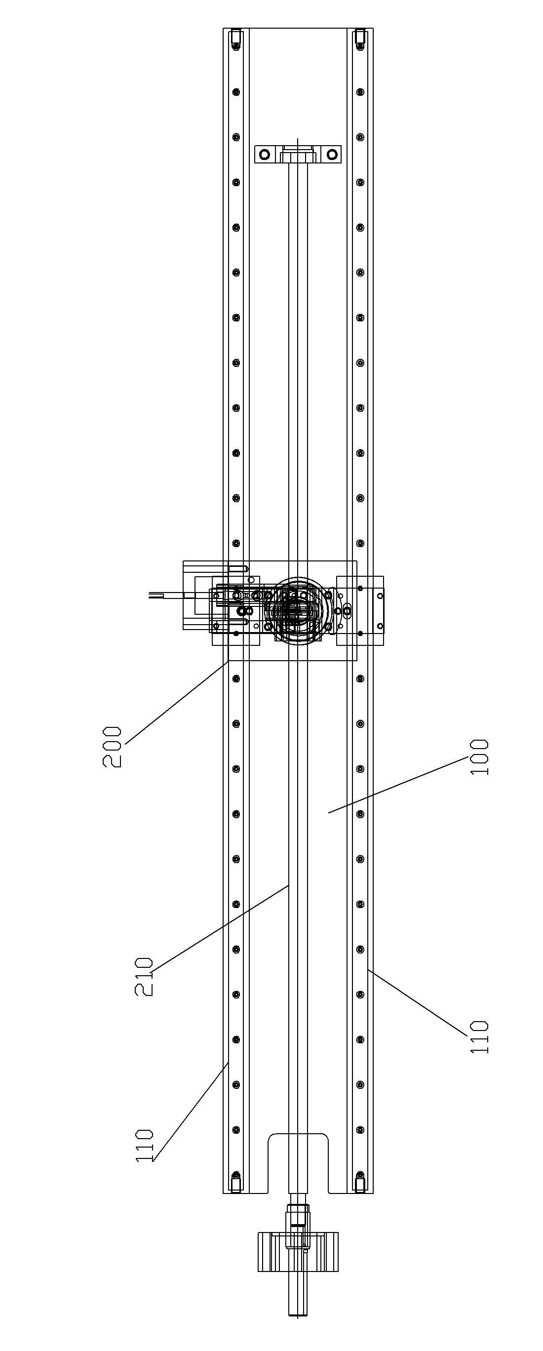
[0030] Please check Figure 1 to Figure 4 , curve cutting equipment, which includes a frame 100, a first unit, a second unit, a knife frame 300, a cutting knife group 400 and a control mechanism. The X-axis, Y-axis, and Z-axis described below can be defined like three-dimensional coordinates. In this embodiment, the cutting device is used for cutting strips for the thin steel plate (to-be-cut object 500 ).

[0031] The first unit is installed on the frame 100 and includes a first power part and a conveying mechanism, and the first power part is connected to the conveying mechanism by transmission so as to make the conveying mechanism move so as to drive the object to be cut to move along the X axis . In this embodiment, the conveying mechanism may be a conveying roller mechanism, a conveyor belt mechanism, a sliding seat mechanism, a hydraulic mechanism, a screw nut mechanism and the like.

[0032] The second unit is installed on the frame 100 and includes a second power pa...


PUM


Abstract

The invention discloses curve cutting equipment which comprises a machine frame (100), two units, a knife rest (300) and a cutting knife group (400). The first unit is installed on the machine frame (100) and comprises a first power part and a conveying mechanism; and the first power part is in transmission connection with the conveying mechanism to move the conveying mechanism and drive a cut object to move along an X axis. The second unit is installed on the machine frame (100) and comprises a second power part and a knife holder (200); and the second power part is in transmission connection with the knife holder (200) to drive the knife holder (200) to move along a Y axis. The knife rest (300) is freely pivoted on the knife holder (200), and a pivot axis is arranged in parallel to a Z axis. The cutting knife group (400) is arranged on the knife rest (300), and a cutting part of the cutting knife group (400) is arranged with the pivot axis of the knife rest (300) in a staggered manner. The curve cutting equipment has the following advantages of smooth cutting edge, simplicity in cutting, low energy consumption and low cost.

Description

technical field [0001] The invention relates to a curve cutting device. Background technique [0002] Since the early cutting settings can only cut straight line slits on the object to be cut, there is a disadvantage that it is impossible to cut curved slits. [0003] Aiming at the above-mentioned deficiencies, someone proposes a solution, which includes a frame, a first unit, a second unit and a cutting knife. The first unit is installed on the frame and includes a first power part and a conveying mechanism, and the first power part is connected to the conveying mechanism by transmission so as to make the conveying mechanism move and drive the object to be cut to move along the X-axis. The second unit is installed on the machine frame and includes a second power element and a knife seat, and the second power element is connected to the knife seat by transmission so as to drive the knife seat to move along the Y-axis. The cutting knife is fixed on the knife seat. Through ...

Claims


Application Information

Patent Timeline
Patent Type & Authority Applications(China)
IPC IPC(8): B23D19/08B23Q1/25
Inventor 黄溢忠黄绛汝程国宝苏瑞旭张建强
Owner XIAMEN ZHENGLIMING METALLURGICAL MACHINERY
Why Eureka
Try Eureka