Automatic bag sleeving device

A bagging device and automatic technology, applied in packaging and other directions, can solve the problems of increased manufacturing cost, low work efficiency, increased failure rate, etc., and achieve the effects of saving energy and manufacturing costs, improving bagging efficiency, and reducing weight

Active Publication Date: 2012-10-31
西安自平机械自动化有限公司
View PDF6 Cites 2 Cited by
  • Summary
  • Abstract
  • Description
  • Claims
  • Application Information

AI Technical Summary

Problems solved by technology

[0002] At present, in chemical fertilizer plants, the plastic bags, woven bags, kraft paper bags or compound bags used are a (single) bag that is formed by shaping (reshaping is called the bag being in the correct position, flat state or shape) to complete the automatic Bagging needs four stations and corresponding devices to realize, that is, one station and one device for the suction bag, one station and one device for the back support of the suction bag (supporting from the inside to the outside), one station and one device for the bag delivery, and one device for the bag receiving , Bagging is another station and one device; the purpose of sucking the bag up to the bag and putting it under the lower hopper is to load the material. The disadvantage is that it has multiple stations and multiple devices, and the technology is relatively backward and the equipment is complicated.
[0003] 1. Complex mechanical structure
If four stations are completed, each station needs a different structure to realize the bagging process. For example, the manipulator and special cylinder not only increase the manufacturing cost, but also use multiple cylinders at the same time, and the mechanical action speed is slow and the failure rate is also greatly increased.
[0004] 2. Low work efficiency
Due to too many links, the action of each link will affect the working efficiency of bagging, so the working efficiency of the whole bagging is low
[0005] 3. Due to multiple special cylinders and multi-link mechanical mechanisms, this kind of automatic bagging cannot be used for long-term trouble-free operation on materials with relatively poor environments, which makes it impossible for many chemical materials to achieve automatic bagging and packaging

Method used


Image

  • Automatic bag sleeving device
  • Automatic bag sleeving device
  • Automatic bag sleeving device

Examples


Embodiment Construction

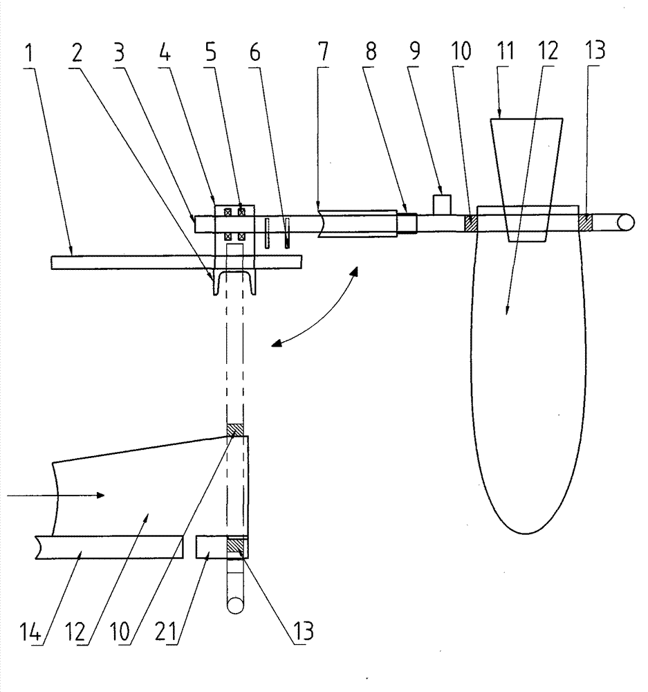
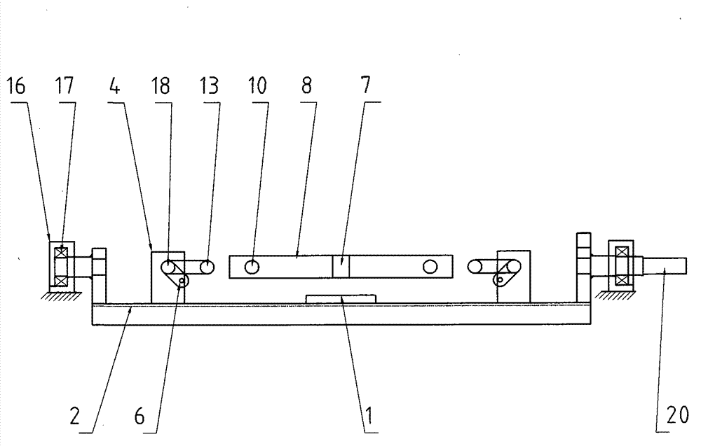
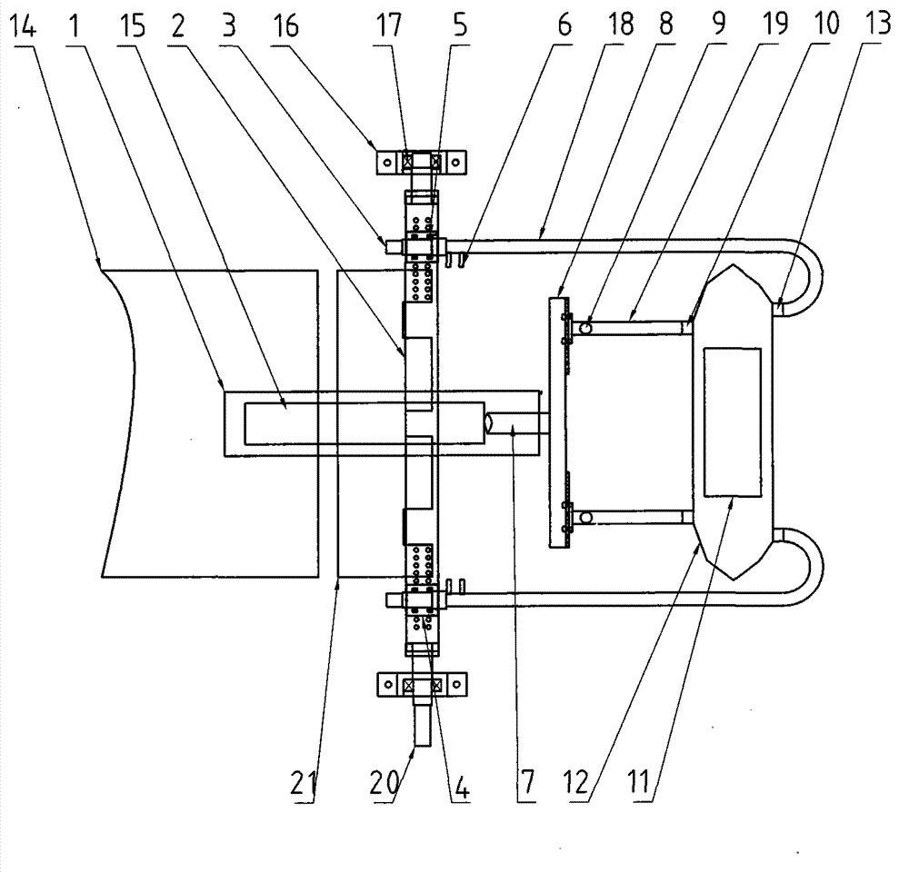
[0029] At first, explain: the inventive point of the present invention is in the bag-loading process, which is to complete the three processes of suction bag, bag opening (or being called as pulling the bag), and bagging (rotating bagging) as one station, and use simple Long and short rods 18 and 19 add suction heads 13 and 10 to realize this process.

[0030] see attached image figure 1 , the two sides of the frame correspond to the fixed bracket shaft bearing seat 16 and the bearing 17, see also Figure 2-Figure 3 , the two-sided symmetrical bearing 17 is equipped with a reciprocating 90° swing or a rotating shaft. The shaft here refers to the input shaft 20, and the inner ends of the input shaft 20 on both sides are connected to the fixed bracket shaft 2. There are three situations: one is that the inner ends of both sides of the input shaft 20 in the shaft are connected to the fixed bracket shaft 2, and the bracket shaft 2 is approximately in the shape of shape to reali...


PUM


Abstract

The invention relates to an automatic bag sleeving device capable of sucking, expending and rotationally sleeving packing bags automatically. In a fertilizer plant in the prior art, the automatic bag sleeving operation of a plastic bag which is in a right position and a flattened state requires four stations and a corresponding device or is fulfilled with about eight manipulators of dedicated cylinders, which causes complexity in mechanical structure and low work efficiency. The invention aims to design the automatic bag sleeving device adopting the structure that an oscillating shaft is fixed on a machine frame; long rods (18) are symmetrically assembled on two sides of the oscillating shaft; the other end of each long rod (18) is a curve arc-shaped end and is fixed with a long rod suction head (13); short rods (19) are fixed at the output of a linear actuating mechanism (15) on a bracket shaft (2) through a linear mechanism connecting rod (7) and a connecting rod (8); and short rod suction heads (10) are fixed at the front ends of the short rods (19). The automatic bag sleeving device is suitable for various environments, particularly for harsh environments, and is high in work efficiency, convenient for integral maintenance and long in service life.

Description

1. Technical field [0001] The invention specifically refers to an automatic bagging device for automatically sucking, stretching, and rotating bagging of packaging bags. 2. Background technology [0002] At present, in chemical fertilizer plants, the plastic bags, woven bags, kraft paper bags or compound bags used are a (single) bag that is formed by shaping (reshaping is called the bag being in the correct position, flat state or shape) to complete the automatic Bagging needs four stations and corresponding devices to realize, that is, one station and one device for the suction bag, one station and one device for the back support of the suction bag (supporting from the inside to the outside), one station and one device for the bag delivery, and one device for the bag receiving 1. Bagging is again a station and a device; the purpose of sucking the bag up to the bag below the lower hopper is to charge the bag. Its weak point is that there are many devices in multiple stations...

Claims


Application Information

Patent Timeline
Patent Type & Authority Applications(China)
IPC IPC(8): B65B43/12B65B43/30B65B43/42
Inventor 郜法军闵红平刘小花郜洋
Owner 西安自平机械自动化有限公司
Why Eureka
Try Eureka