Supercharge Your Innovation With Domain-Expert AI Agents!

Anti-seismic beam-column joint column hoop fixing method and structure

A fixing method and technology of beam-column joints, which are applied in the directions of earthquake resistance, building components, building structures, etc., can solve the problems of insufficient quantity, dense stirrups outside the column, and uneven spacing, so as to achieve simple structure and process, and ensure construction quality. , the effect of design quality assurance

Inactive Publication Date: 2012-10-31
CHINA CONSTR FOURTH ENG DIV
View PDF4 Cites 0 Cited by
  • Summary
  • Abstract
  • Description
  • Claims
  • Application Information

AI Technical Summary

Problems solved by technology

When arranging the outer stirrups of the column, due to the criss-crossing of the beams, the reserved outer stirrups are often deformed when the beam is put into the mold, and the reserved amount is not accurate, and the position is wrong, resulting in too dense or loose column outer stirrups. It can't play its due role, but because the stirrups outside the column are too concentrated, the concrete that will be poured overhead will bury hidden dangers to the quality of the beam-column joints
In the actual construction of the beam-column joint area, there are often lack of binding of the outer stirrups of the column, insufficient quantity, uneven spacing, or multiple stirrups piled up together, so that some column bars have no stirrups for a long period of time. These problems are not necessary. It is beneficial to the earthquake resistance of the frame structure and affects the safety of the building

Method used


Image

  • Anti-seismic beam-column joint column hoop fixing method and structure
  • Anti-seismic beam-column joint column hoop fixing method and structure
  • Anti-seismic beam-column joint column hoop fixing method and structure

Examples


Embodiment Construction

[0029] The present invention will be further described in detail below in conjunction with the accompanying drawings and embodiments.

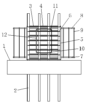
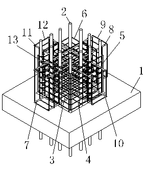
[0030] A kind of anti-seismic beam-column node column hoop fixing method of the present invention, such as figure 1 , 2 and 3 are shown. The method is constructed in the following steps:

[0031] ①. First, tie or weld a set of inner stirrups according to the designed spacing on a set of column bars 2 that run through the floor formwork surface 1 (see Figure 5 );

[0032] ②. Put the pre-tied or welded column outer stirrup cage from the top of a group of column bars 2 on the outside of a group of column bars 2, and adjust the column outer stirrup cage according to the design requirements (see Figure 4 ), then bind or weld the outer stirrup cage and the inner stirrup;

[0033] ③. Position and connect the X-direction beam reinforcement at one end (refer to Figure 6 ) horizontally pass through the gap between a group of column ...


PUM


Abstract

The invention discloses an anti-seismic beam-column joint column hoop fixing method and structure. The anti-seismic beam-column joint column hoop fixing method comprises the following steps of: binding or welding a group of internal hooping bars at designed interval on a group of column bars penetrating through a storey formwork surface; then binding or welding a column external hooping bar cage and internal hooping together; and then positioning and connecting the other ends of the X-direction beam bars. According to the invention, a column external hooping bar cage construction method is adopted, and distances among the external hooping bars are fixed by limiting bars at the outer sides of corners of the column bars. The anti-seismic beam-column joint column hoop fixing method and structure have the advantages of simple structure and process and convenience for operation and the like, effectively ensure design quality and can eliminate hidden quality hazards having influence on concrete construction and ensure that deviation of the vertical steel bars cannot happen. The anti-seismic beam-column joint column hoop fixing method and structure solve the problems that the beam-column joint hooping bars are not bound, are not sufficient in quantity and are not distinct in gaps, or a plurality of hooping bars are piled together, or no hooping bars exist in an empty section and the like in the binding process under the adverse factors of small size of a joint and dense steel bars in the construction process of beam-column joints.

Description

technical field [0001] The invention relates to a method and a structure for fixing a hoop of an aseismic beam-column node, and belongs to the technical field of construction. Background technique [0002] With the rapid development of my country's construction industry, frame structure buildings have been widely used in multi-storey and high-rise buildings due to their good earthquake resistance. The key anti-seismic points of the frame structure are the foundation and the beam-column structure. According to the damage investigations of previous earthquakes, it is shown that when an earthquake occurs, most of the frame structure buildings occur in the joint area of ​​beams and columns, and the joint damage is mainly oblique shear failure and reinforcement anchorage failure, until the entire frame structure collapses. Therefore, the beam-column joints of the frame structure, as the core area of ​​the joints, should have sufficient strength and necessary plasticity. From th...

Claims


Application Information

Patent Timeline
Patent Type & Authority Applications(China)
IPC IPC(8): E04B1/41E04B1/58E04B1/98
Inventor 张明施振生陈逸宾
Owner CHINA CONSTR FOURTH ENG DIV
Features
  • R&D
  • Intellectual Property
  • Life Sciences
  • Materials
  • Tech Scout
  • Unparalleled Data Quality
  • Higher Quality Content
  • 60% Fewer Hallucinations
Learn More