
Refrigerating air conditioning device and refrigerating air conditioning system

A technology for an air-conditioning device and a heat exchange unit, which is applied in the fields of refrigeration and air-conditioning systems and refrigeration and air-conditioning devices, can solve the problems of troublesome piping construction, difficult maintenance and maintenance, and inability to ensure the suction surface of external air, and achieves simplified construction, maintenance, and easy maintenance. Effect

Active Publication Date: 2012-10-31
MITSUBISHI ELECTRIC CORP
View PDF9 Cites 0 Cited by
  • Summary
  • Abstract
  • Description
  • Claims
  • Application Information

AI Technical Summary

Problems solved by technology

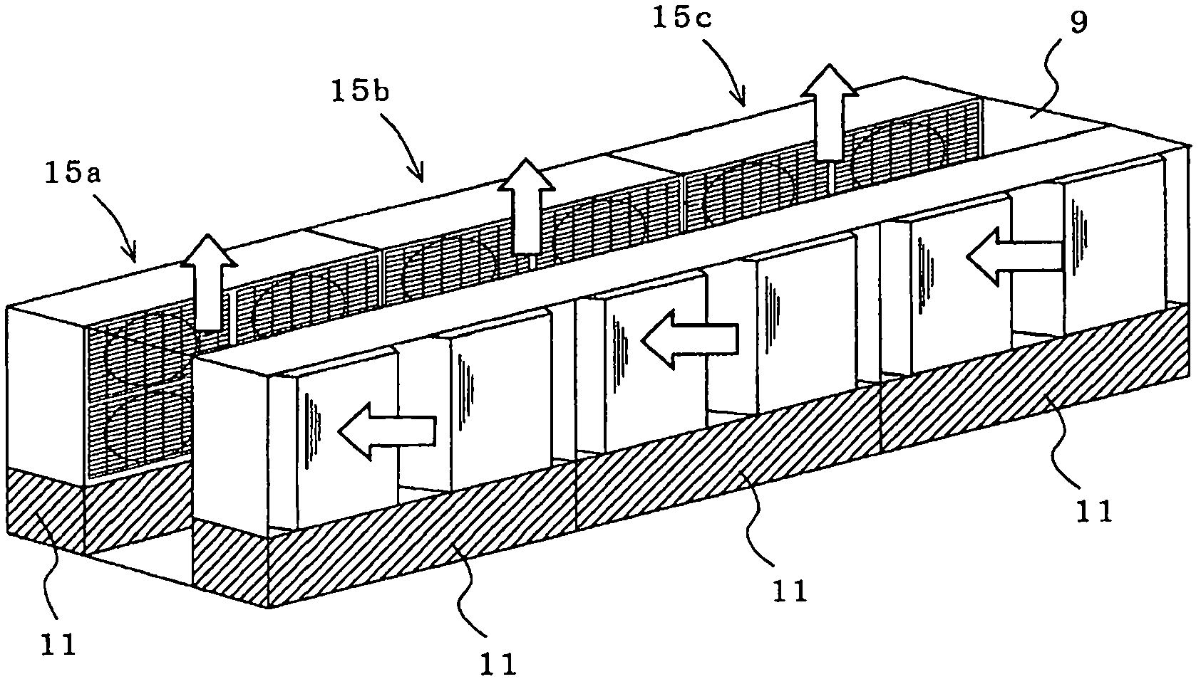
[0006] According to the refrigerating and air-conditioning apparatus of Patent Document 1, even if a strong external wind blows to the refrigerating and air-conditioning apparatus 15, due to the blown air flow C of the two fans 5 1 、C 2 As a resistance, it can also prevent external wind from blowing into the heat exchange units 1a to 1d, so it can prevent performance degradation and reliability degradation such as a decrease in condensation pressure and a decrease in refrigerant capacity. However, for example, Figure 12 As shown, if the refrigerating and air-conditioning devices 15a, 15b, and 15c are installed consecutively, there is a problem that the refrigerating and air-conditioning device 15b sandwiched by the refrigerating and air-conditioning devices 15a and 15c on both sides cannot ensure the suction surface of the outside air.
[0007] Additionally, if Figure 13 As shown, if the piping 20 is installed near the refrigerating and air-conditioning device 15 on site, the air C blown out from the outlet 4 of the heat exchange unit 1 near the piping 20 may hit the piping 20 and be screwed into the suction port 3. Side blown air short cycle (short cycle)
[0008] In addition, if Figure 14 As shown, when refrigerating and air-conditioning apparatuses 15a and 15b composed of a plurality of heat exchange unit assemblies 10 are stacked in multiple layers (two layers are illustrated in the figure) and air discharge ducts 21 are provided on both sides thereof , not only the discharge pipe 21 becomes large, but also the piping 20 must penetrate the discharge pipe 21, so the structure of the discharge pipe 21 becomes complicated
[0009] In addition, not only the piping construction in the discharge pipe 21 is troublesome, but also the repair and inspection of the pipe 20 cannot be performed unless it enters the discharge pipe 21, so repair and maintenance are difficult.

Method used


Image

  • Refrigerating air conditioning device and refrigerating air conditioning system
  • Refrigerating air conditioning device and refrigerating air conditioning system
  • Refrigerating air conditioning device and refrigerating air conditioning system

Examples


Embodiment approach 1

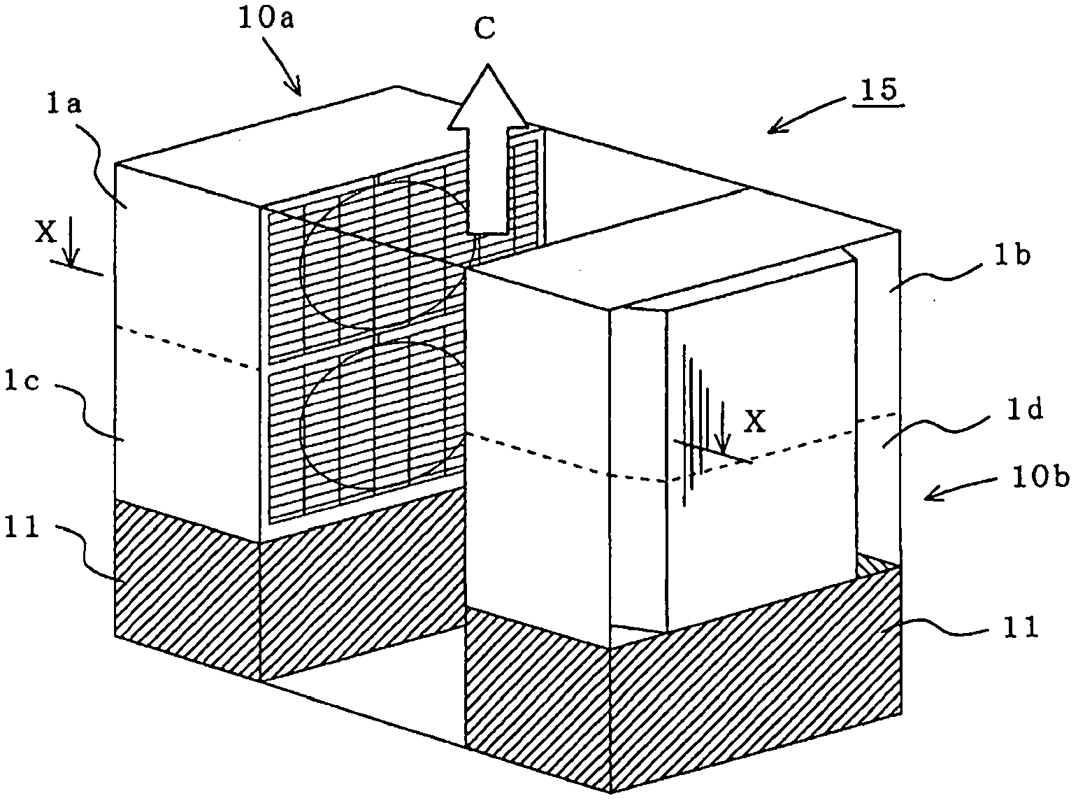
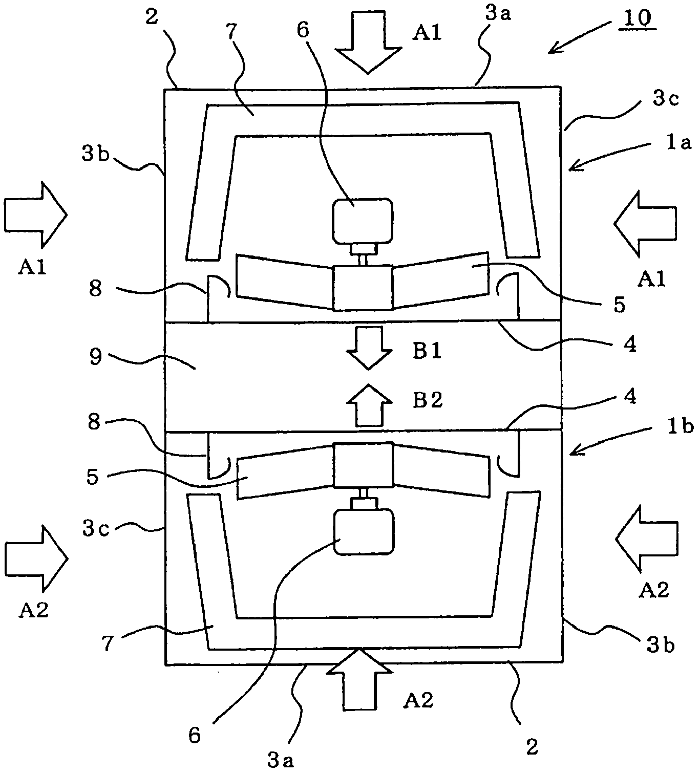
[0030] figure 1 It is an explanatory diagram of the refrigerating and air-conditioning apparatus according to Embodiment 1 of the present invention, figure 2 yes figure 1 The X-X section view.

[0031] In both drawings, reference numerals 1a, 1b, 1c, and 1d denote heat exchange units (hereinafter, may be denoted only by reference numeral 1), and the front surface and both sides of the box-shaped housing 2 are provided with a heat exchange unit. The suction ports 3a, 3b, and 3c (hereinafter, may be indicated only by reference numeral 3) are provided with an air blower port 4 on the back side. In addition, the suction port 3 may be provided only on the front according to circumstances.


PUM


Abstract

The invention provides a refrigerating air conditioning device which prevents short cycle when air is blown out, enables the structure of exhaust pipes stacked into multiple layers to be small and simplified, and realizes easy piping construction and maintenance, and a refrigerating air conditioning system using the refrigerating air conditioning device. The refrigerating air conditioning device comprises heat exchange units (1). In each heat exchange unit, a propeller type fan (5) is disposed in a box-shaped casing at least comprising suction inlets (3) on the front surface side and a blow-off outlet (4) on the back side in a manner that the fan faces the blow-off outlet (4), and a heat exchanger (7) is disposed on the suction inlet (3) side. The refrigerating air conditioning device comprises a heat exchange unit assembly (10) formed by arrangement of the heat exchange units (1) in a manner that the heat exchange units (1) are separated from each other by a ventilation passage (9) and the blow-off outlets (4) of the heat exchange units (1) face each other.

Description

technical field [0001] The present invention relates to a refrigerating and air-conditioning device composed of a plurality of heat exchange units and a machine room, and a refrigerating and air-conditioning system using the refrigerating and air-conditioning device. Background technique [0002] When expressing the conventional refrigeration and air-conditioning equipment Figure 10 , Figure 11 In the heat exchange units 1a, 1b, which are provided with suction ports 3a, 3b, 3c for outdoor air on both side walls and the rear wall of a box-shaped casing (casing) 2, and provided with air outlets 4 on the front surface side, A propeller fan 5 driven by a fan motor 6 is provided facing the air outlet 4 , and a substantially U-shaped heat exchanger 7 is arranged on the back side of the propeller fan 5 . Reference numeral 8 denotes a bell mouth provided at the air outlet 4 so as to surround the propeller fan 5 . [0003] Such as Figure 11 As shown, the heat exchange unit asse...

Claims


Application Information

Patent Timeline
IPC IPC(8): F24F13/30F24F13/20
Inventor 大塚修伊藤拓也七种哲二大越靖石田和之杉野雅彦宫本守也
Owner MITSUBISHI ELECTRIC CORP
Learn More