
Wireless power supply control system and control method

A power control and control signal technology, applied in the computer field, can solve the problems of increasing complexity, cost and wiring overhead, out-of-band management can not effectively complete the task, power management system scalability is not involved, etc., to achieve channel quality And channel utilization efficiency is improved, wireless signal interference is small, and the effect of improving security

Active Publication Date: 2012-10-31
JIANGNAN INST OF COMPUTING TECH
View PDF4 Cites 8 Cited by
  • Summary
  • Abstract
  • Description
  • Claims
  • Application Information

AI Technical Summary

Problems solved by technology

However, with the popularization of data centers, the scale of computer clusters is getting larger and larger, and the traditional out-of-band management of mechanical switches cannot effectively complete the task. Therefore, the remote power management network system came into being
[0004] For now, most of the network of the general remote power management system is realized by wire. However, with the increase of the scale of the computer cluster, the complexity, cost and wiring overhead of the network are also increasing. In order to solve the Problems in network cost and wiring overhead, and some remote power management system networks use wireless transmission control signals, such as the Chinese patent with the announcement number CN2879275 discloses a power management device with wireless control function, but it only involves In addition to using a wireless network to transmit control signals, how to improve the scalability and transmission security of the power management system has not been involved.

Method used


Image

  • Wireless power supply control system and control method
  • Wireless power supply control system and control method
  • Wireless power supply control system and control method

Examples


Embodiment Construction

[0056] As mentioned in the background technology, although the power management system of the prior art uses a wireless method to transmit control signals to manage the power supply of the computer, its control terminal directly transmits control signals to the power control switch in a wireless manner. , by controlling the power control switch to control the opening and closing of the computer connected to it. However, the power management system networked in the above-mentioned manner has poor scalability, low security, high power required for transmission of control signals, low channel utilization rate and low network capacity of the wireless network.

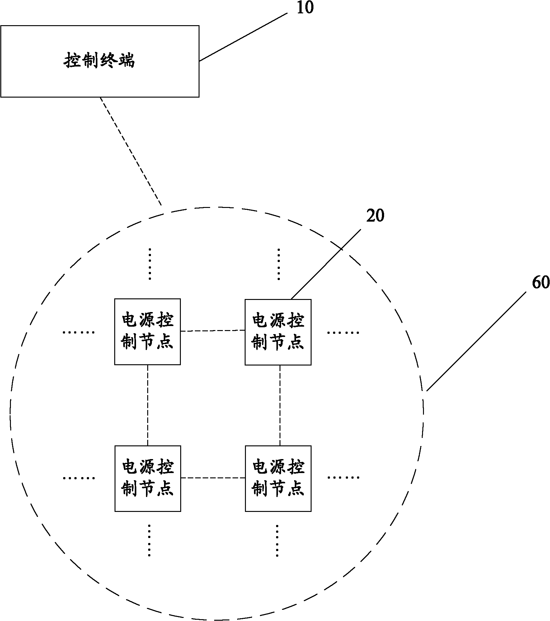
[0057] The power control system in the embodiment of the present invention connects multiple power control nodes through a wireless grid network, which improves the performance and scalability of the power control system, and improves the reliability of the wireless network where the power control nodes in the power control ...


PUM


Abstract

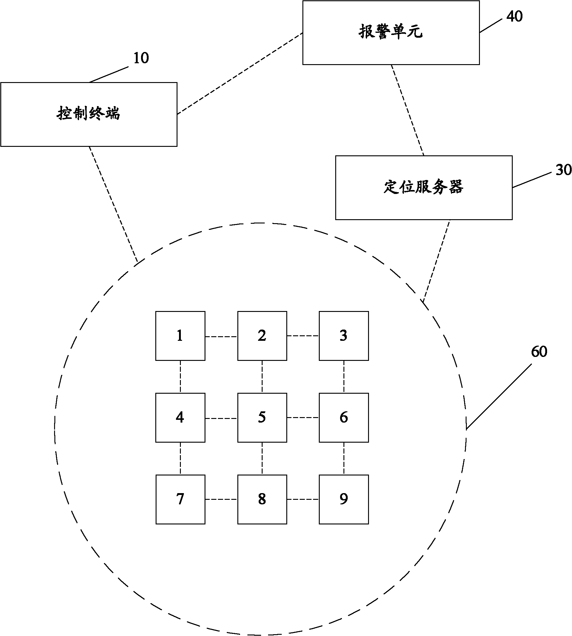
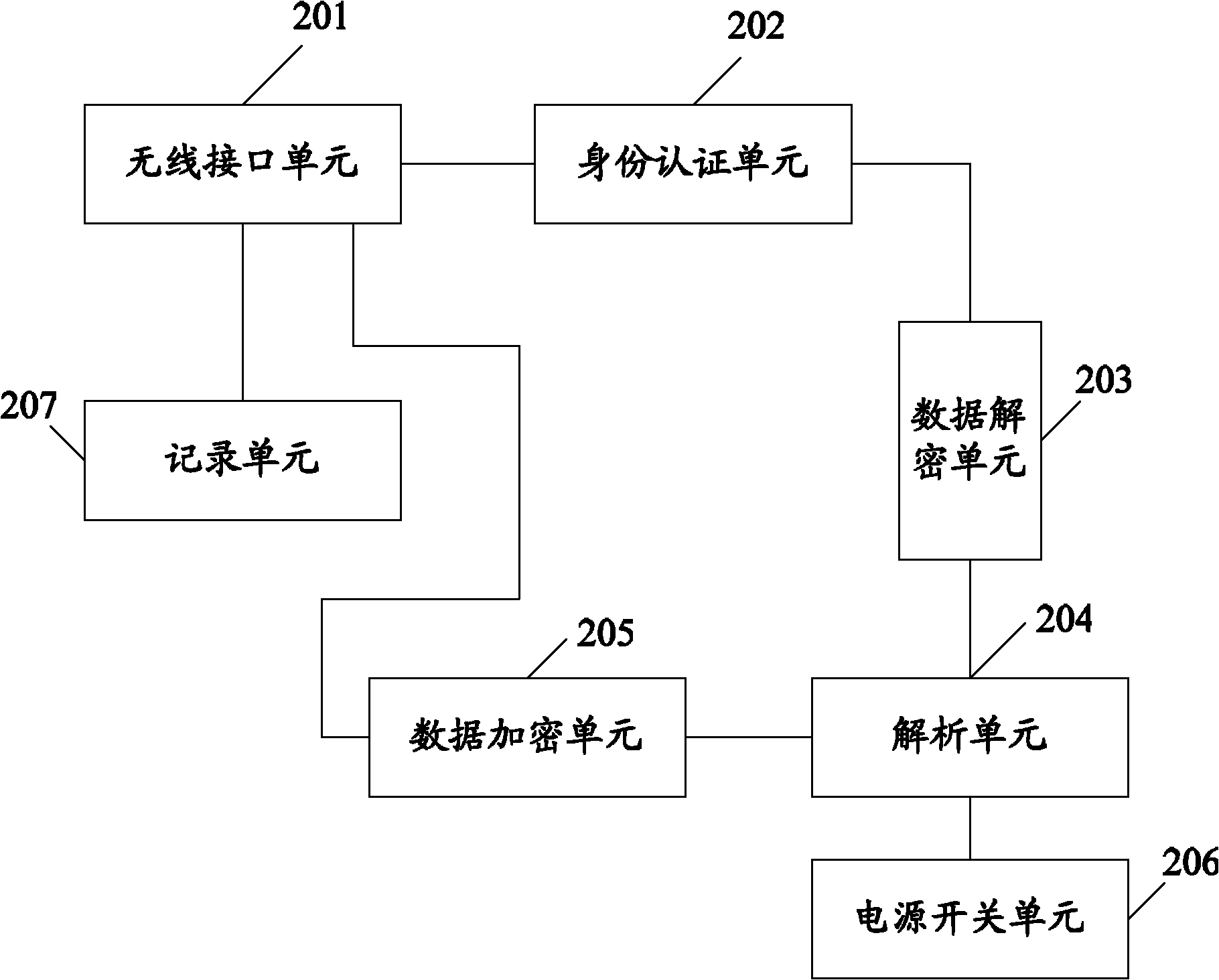
The invention discloses a power supply control system and control method. The power supply control system is used for controlling the opening or closing of computer nodes in a computer cluster system and comprises a control terminal and a plurality of power supply control nodes connected by a wireless grid network, wherein the control terminal is suitable for acquiring route information and transmits a control signal to the power supply control nodes in a wireless way; the control signal carries an active address, a destination address, route information and information for the computer nodes to be controlled; the power supply control nodes are connected between the control terminal and the computer nodes, is suitable for receiving and analyzing the control signal and controlling the opening or closing of the corresponding computer nodes on the basis of the information for the computer nodes to be controlled; and when the power supply control nodes are the power supply control nodes pointed by the destination address, the power supply control nodes forward a control signal to the wireless grid network on the basis of the analyzed route information. The power supply control system has the advantages of strong extensibility and high safety.

Description

technical field [0001] The invention relates to the field of computer technology, in particular to a wireless power supply control system and a control method. Background technique [0002] There are two types of power management for computer systems: in-band management and out-of-band management. The so-called in-band management means that the control input of the power management system comes from the local system, that is, the power supply of the computer system is controlled through the local system software (mainly through the operating system). Using in-band management can control the power supply of the computer system more conveniently, and because the in-band management is controlled by the computer system software, it can flexibly complete operations such as on, off, restart, and even voltage adjustment according to software instructions. However, in-band management also has certain defects. Because its management of the power supply of the computer system complet...

Claims


Application Information

Patent Timeline
Patent Type & Authority Applications(China)
IPC IPC(8): G06F1/26
Inventor 谢向辉吴东方兴原昊张昆藏春峰李达哲张健
Owner JIANGNAN INST OF COMPUTING TECH
Learn More