
Hand-free ternary inspection machine

A technology of inspection machine and lifting mechanism, applied in the field of chip welding and wire bonding, can solve the problems of increasing artificially bumped products, deformation of welding wires in the state of chip bonding, and no direct connection, so as to avoid manual direct contact with packaged products and satisfy the The effect of safety protection requirements

Inactive Publication Date: 2012-10-31
上海功源电子科技有限公司
View PDF1 Cites 5 Cited by
  • Summary
  • Abstract
  • Description
  • Claims
  • Application Information

AI Technical Summary

Problems solved by technology

[0004] However, the traditional optical inspection equipment is not directly connected with the material box that stores the product to be inspected, and the operator needs to manually remove the material strip from the material box, and then place it on the inspection table for inspection
In this way, on the one hand, the static electricity on the human body, sweat stains, dust, and body fluids on the hands are likely to affect and contaminate the lead frame and new products; on the other hand, manual contact inevitably increases the chance of artificially damaging the product; In the way of manually holding the lead frame, most areas on the frame will bend and sag due to gravity, and the chips and bonding wires on the surface will be pulled to varying degrees, resulting in the deformation of the bonding state of the chip and the bonding wire
This kind of deformation occurs precisely during the transfer process of the strip, therefore, the subsequent detection will not accurately reflect the actual production situation of the product, and the adjustment of technicians and production equipment will produce wrong guidance

Method used


Image

  • Hand-free ternary inspection machine

Examples


Embodiment Construction

[0010] Below in conjunction with accompanying drawing and specific embodiment the present invention is described in further detail:

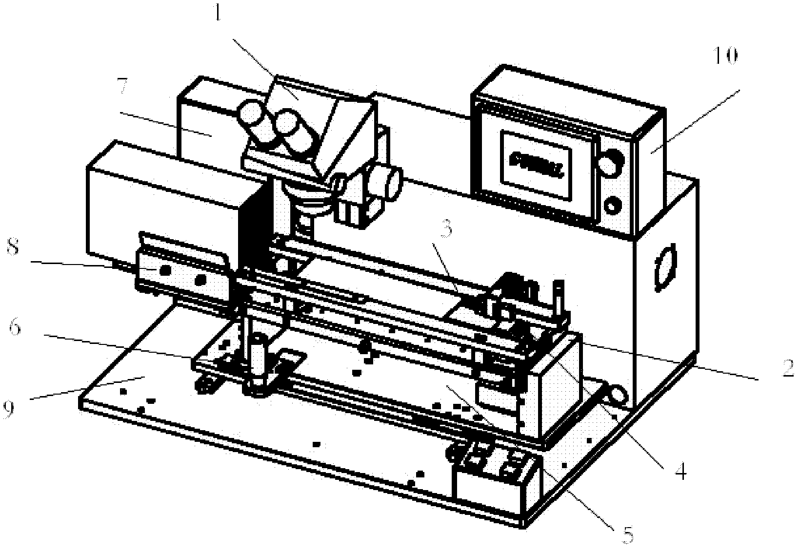
[0011] Depend on figure 1 It can be seen that the present invention includes: a stereoscopic microscope 1; also includes: an X-axis guide rail 2 and a moving claw 3 on the X-axis guide rail 2; the X-axis guide rail 2 can move in steps; The claw 3 clamps the material strip through a pneumatic feeding mechanism 4 arranged on the X-axis guide rail; a guide rail width adjustment assembly 5 is also arranged on the X-axis guide rail 2; it also includes: an X, Y manual moving table 6 ; The described X, Y manual mobile platform 6 is placed on the base plate 9; a material box elevating mechanism 7 arranged on the X, Y manual mobile platform 6 and a material box holder arranged on the material box elevating mechanism 7 8; The X-axis guide rail 2, the material box lifting mechanism 7 and the pneumatic feeding mechanism 4 are connected to a PLC 10 respecti...


PUM


Abstract

The invention relates to a hand-free ternary inspection machine, which comprises a stereomicroscope, an X-axis guide rail and moving claws on the X-axis guide rail, an X-axis and Y-axis manual mobile table, a material box lifting mechanism and a material box clamping device, wherein the X-axis guide rail can move in a stepping manner; the moving claws on the X-axis guide rail are used for clamping bars by a pneumatic feeding mechanism on the X-axis guide rail; a guide rail width adjusting assembly is also arranged on the X-axis guide rail; the X-axis and Y-axis manual mobile table is arranged on a bottom plate; the material box lifting mechanism is arranged on the X-axis and Y-axis manual table and the material box clamping device is arranged on the material box lifting mechanism; and the X-axis guide rail, the material box lifting mechanism and the pneumatic feeding mechanism are respectively connected with a PLC (Programmable Logic Controller). The hand-free ternary inspection machine disclosed by the invention has the beneficial effects of completely preventing personnel from being in direct contact with a packaged product by using a convenient PLC-based control technology and meeting the safety protection requirement.

Description

technical field [0001] The invention relates to a chip welding and welding wire of a semiconductor lead frame, in particular to a detection device for the chip welding and welding wire of the semiconductor lead frame. Background technique [0002] In the semiconductor packaging industry, the purpose of die bonding is to place individual dies on a lead frame or substrate (PCB) and fix them with silver glue (epoxy). The lead frame or substrate provides a place for the die to stick to (die pad), and is preset with extension feet or pads that can extend the circuit of the IC die. The purpose of the wire bonding is to connect the contacts on the die to the internal pins on the lead frame or the substrate with a very thin gold wire (18-50um), so as to transmit the circuit signal of the IC die to the external wire bonding. The contact on the die is the first soldering point, and the contact on the inner pin is the second soldering point. First, the ends of the gold wires are sint...

Claims


Application Information

Patent Timeline
Patent Type & Authority Applications(China)
IPC IPC(8): H01L21/66
Inventor 卢冬青
Owner 上海功源电子科技有限公司
Learn More