Nox elimination injector firing control circuit

A technology of ignition control and injectors, which is applied in the direction of mufflers, machines/engines, chemical instruments and methods, etc., can solve problems such as sensitive lift tolerances, and achieve the effect of improving the closing response

Inactive Publication Date: 2014-12-24
TENNECO AUTOMOTIVE OPERATING CO INC
View PDF8 Cites 0 Cited by
  • Summary
  • Abstract
  • Description
  • Claims
  • Application Information

AI Technical Summary

Problems solved by technology

Known injectors are sensitive to lift tolerances

Method used


Image

  • Nox elimination injector firing control circuit
  • Nox elimination injector firing control circuit
  • Nox elimination injector firing control circuit

Examples


Embodiment Construction

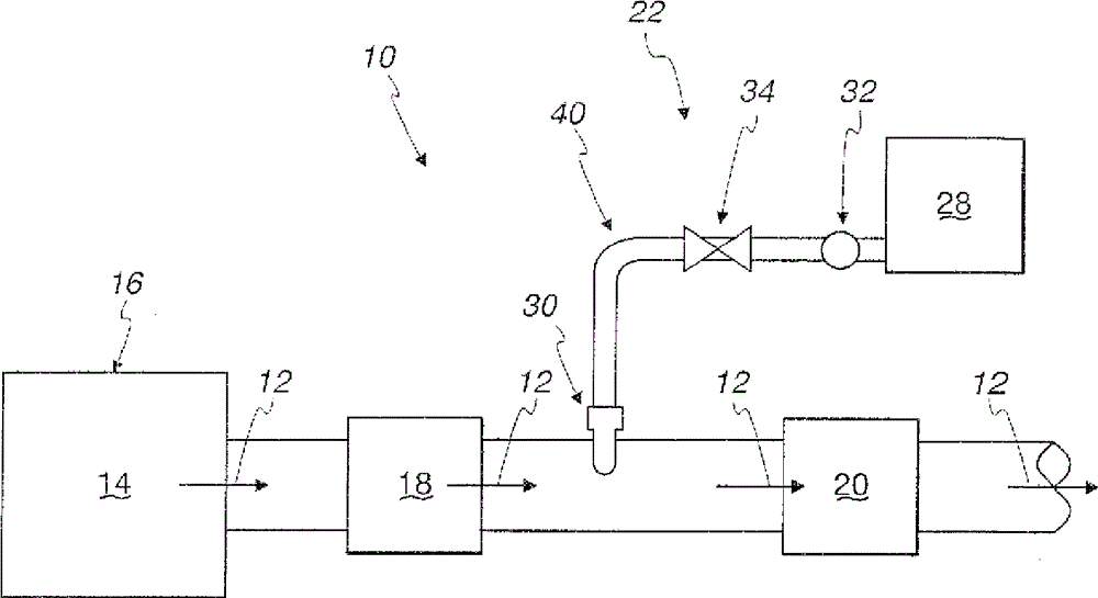
[0020] refer to figure 1 , a diesel exhaust aftertreatment system 10 is provided to treat emissions 12 from a diesel combustion process 14 (eg, a diesel compression engine 16 ). System 10 may include one or more exhaust treatment components 18 that clean and / or treat exhaust gas 12 , such as a diesel particulate filter (DPF), a combustor, a diesel oxidation catalyst (DOC), a lean NOx trap, and the like. There are many suitable types of configurations for such components, the choice of which is highly dependent on the parameters of each particular application.

[0021] System 10 also includes a selective catalytic reduction catalyst (SCR) 20 and a urea injection system 22 for injecting urea 24 into exhaust 12 upstream of SCR 20 . The urea injection system 22 will typically include a tank 28 or other type of container for the urea 24, one or more urea injectors 30, a pump 32 for pressurizing the urea 24 in the system 22, a pump 32 for controlling the A control valve 34 for the...


PUM


Abstract

An NOx injection system for treating a vehicle exhaust system comprises an injector for injecting a select material into the vehicle exhaust system and including an electrical coil. An impedance element is connected in series with a flyback diode across the coil. An injector firing control circuit is electrically connected to the injector for driving the coil, the switching circuit operating in an on mode to fire the injector and in an off mode to turn off the injector. The impedance element increases reverse voltage to increase injector turn off response.

Description

[0001] Cross References to Related Applications [0002] There are no related applications. technical field [0003] The present invention relates to systems and methods for eliminating nitrogen oxides in vehicle exhaust systems, and more particularly to injector firing control circuits that provide rapid opening and closing of injectors. Background technique [0004] Vehicle exhaust aftertreatment systems are known to treat emissions from combustion processes such as compression engines. The system may include an exhaust treatment component that cleans or treats exhaust. One such known system is a urea injection system for eliminating or reducing NOx (nitrogen oxides) from the exhaust. The injection system injects urea into the exhaust. The injector includes an electric solenoid with a coil fired by the injector control circuit. The injectors are typically driven by a pulse width modulated control signal operable on the order of eg 5 Hz with relative on and off times co...

Claims


Application Information

Patent Timeline
Patent Type & Authority Patents(China)
IPC IPC(8): B01D53/90
CPCY02T10/24F01N3/208Y02A50/20Y02T10/12B01D53/00B01D53/90B01D53/94F01N3/10
Inventor S.托马斯J.雷诺S.凯德尔M.肖弗尔斯
Owner TENNECO AUTOMOTIVE OPERATING CO INC
Why Eureka
Try Eureka