
Diesel engine

A technology of diesel engine and timing mechanism, applied in engine components, combustion engine, engine control and other directions, can solve problems such as poor fuel consumption, large amount of black smoke, incomplete combustion, etc.

Active Publication Date: 2015-05-06
YANMAR POWER TECHNOLOGY CO LTD
View PDF7 Cites 2 Cited by
  • Summary
  • Abstract
  • Description
  • Claims
  • Application Information

AI Technical Summary

Problems solved by technology

This so-called timing delay is a technique for reducing the maximum combustion temperature by delaying the ignition time, and suppressing the reaction of nitrogen and oxygen to reduce the amount of NOx produced. However, at this time, due to the fuel supplied after the initial combustion that reaches the maximum combustion temperature Therefore, the combustion becomes incomplete, the fuel consumption is poor, and the amount of black smoke is also large.

Method used


Image

  • Diesel engine
  • Diesel engine
  • Diesel engine

Examples


Embodiment Construction

[0038] Next, embodiments of the invention will be described.

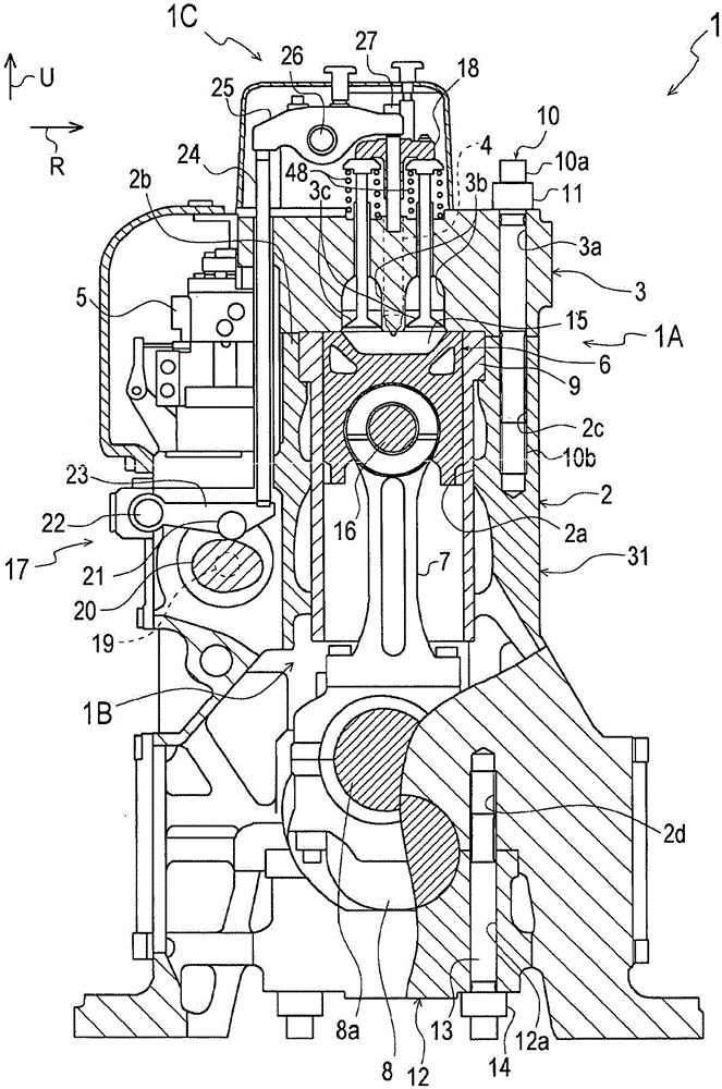
[0039] Additionally, the figure 1 The direction indicated by the arrow U of 2 is taken as the upper side of the diesel engine 1, and the direction indicated by the arrow R is taken as the right side of the diesel engine 1, and the positions and directions of the various components described below will be described.

[0040] First, use figure 1 The overall structure of the diesel engine 1 according to the present invention will be described. In addition, in the diesel engine 1 , since the configurations of the respective cylinders are substantially the same, only one of the cylinders will be described.

[0041] The diesel engine 1 is composed of the following parts: the engine main body 1A such as the cylinder 31 constituted by the cylinder block 2 and the cylinder head 3; and the fuel injection nozzle 4, the fuel injection pump 5, and the intake and exhaust valve drive section 1C.

[0042] In the engine main bo...


PUM


Abstract

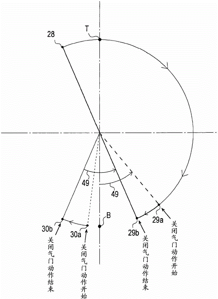
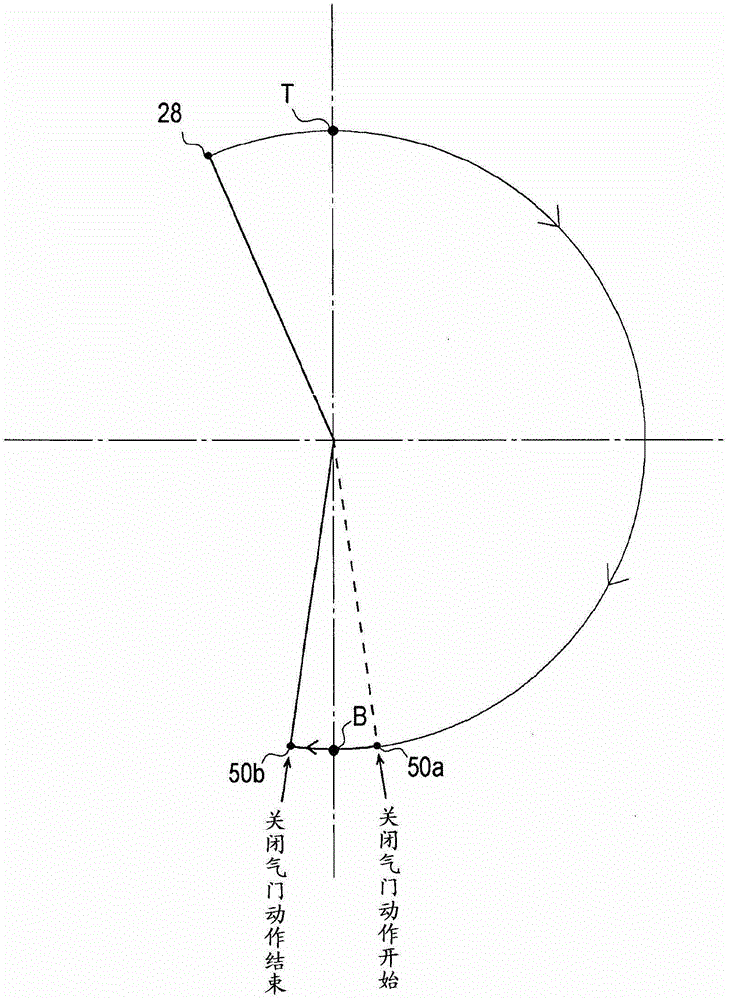
A diesel engine (1) configured so that fuel spray patterns (45, 46) are formed in a combustion chamber (15), in which the swirl flow (W) of intake air is being generated, by directly injecting the fuel from a fuel injection nozzle (4) having a multiple nozzle hole structure. The diesel engine (1) is provided with a superposition avoidance structure for reducing the superposition of the fuel spray patterns (45, 46) emitted from adjacent nozzle holes (34a, 35a). A valve timing mechanism (17) is provided as the superposition avoidance structure, and the valve timing mechanism (17) sets the timing (29a, 50a, 51 a), which is the start point of the valve closing operation of air intake valves (3c, 3c) for sucking air into the combustion chamber (15), to a point before the bottom dead center (B) of air intake. Also, the valve closing operation is provided with a buffering section (52) in which the seating speed of the air intake valves (3c, 3c) is reduced to buffer the impact of the seating, and the timing (51c) which is the start point of the buffer section (52) is set to a point before the bottom dead center (B) of air intake.

Description

technical field [0001] The present invention relates to a direct-injection type in which fuel is directly injected into the combustion chamber from a fuel injection nozzle having a multi-jet structure by causing the air sucked into the combustion chamber to rotate horizontally to generate a swirling swirling flow (hereinafter referred to as "vortex"). Diesel engines, in particular, relate to combustion technologies capable of reducing NOx without incurring deterioration of fuel consumption and increase in the amount of black smoke. Background technique [0002] Conventionally, in a direct-injection diesel engine that injects fuel directly into a combustion chamber to perform self-ignition, timing retardation is known as a technique for reducing the amount of NOx produced. This so-called timing delay is a technique to reduce the maximum combustion temperature by delaying the ignition time, and suppress the reaction of nitrogen and oxygen to reduce the amount of NOx produced. ...

Claims


Application Information

Patent Timeline
Patent Type & Authority Patents(China)
IPC IPC(8): F02D13/02F01L1/08F02D41/02F02M61/18
CPCF01L1/08F01L1/146F01L1/16F01L1/18F01L1/181F01L1/267F01L2001/054F01L2003/253F02B3/06F02B23/0624F02B23/0636F02B23/0669F02B2275/14F02D13/0234F02D13/0257F02D2041/001F02D2041/389F02M61/1813F02M61/182F01L2305/00Y02T10/12F02D13/02F02D41/02F02M61/18
Inventor 滨冈俊次古东文哉半田哲士表洪志
Owner YANMAR POWER TECHNOLOGY CO LTD
Learn More