Hydraulic forming device and method of reducing cylindrical part

A technology for hydroforming and cylindrical parts, applied in the field of hydroforming devices, can solve the problems of high cost, difficult to process and form, poor forming performance, etc., and achieve the effect of improving production efficiency and overall quality, and being easy to disassemble

Inactive Publication Date: 2012-11-07
HARBIN INST OF TECH
View PDF7 Cites 31 Cited by
  • Summary
  • Abstract
  • Description
  • Claims
  • Application Information

AI Technical Summary

Problems solved by technology

[0005] In order to solve the problem that the traditional plate hydraulic deep drawing method is difficult to process and form the variable-diameter cylindrical parts whose outer diameter gradually decreases from the bottom upward or in a stepped shape, the roll welding process has high cost, long cycle, and The bottleneck problem of poor forming performance, and then provides a hydroforming device and method for a cylindrical part with reduced diameter

Method used


Image

  • Hydraulic forming device and method of reducing cylindrical part
  • Hydraulic forming device and method of reducing cylindrical part
  • Hydraulic forming device and method of reducing cylindrical part

Examples


specific Embodiment approach 1

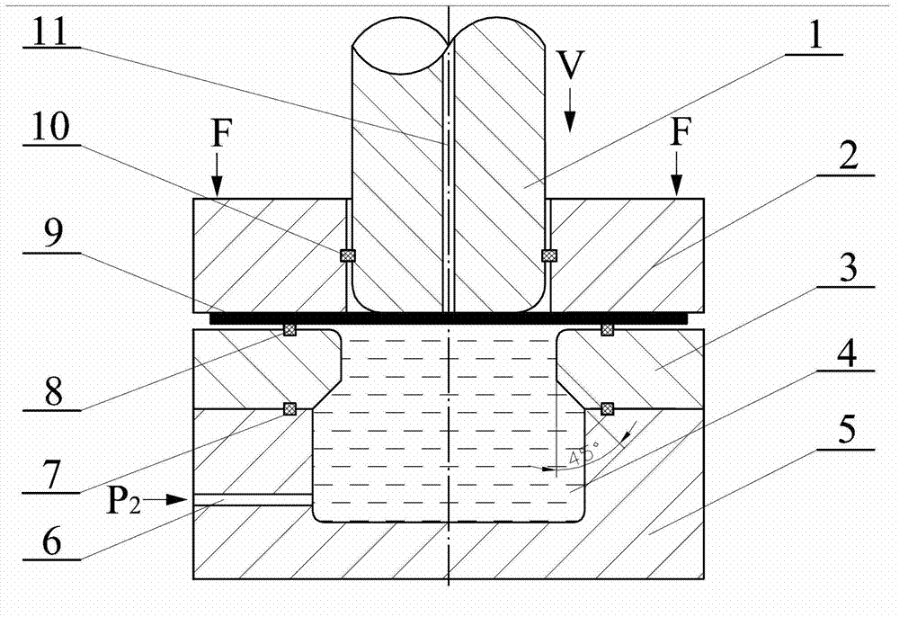
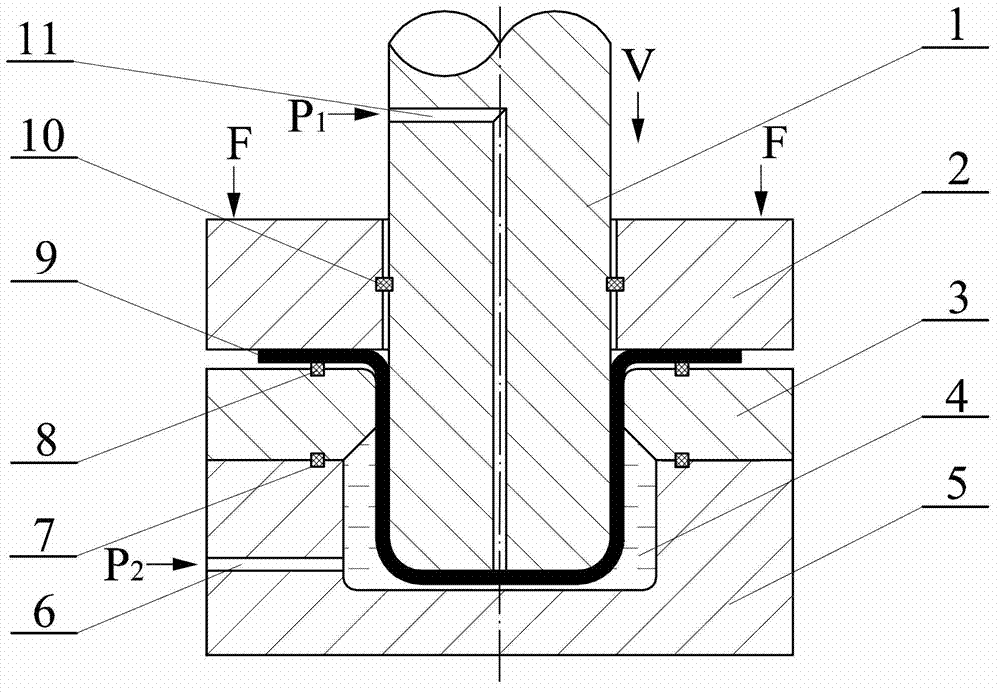
[0017] Specific implementation mode one: the following combination figure 1 , figure 2 and image 3This embodiment will be specifically described. The device includes a lower die 5, which is provided with an injection hole 6 communicating with the force transmission medium cavity 4, and injects the force transmission medium into the lower die 5 through the injection hole 6 during operation; the lower die 5. The upper end is open, and the lower die 5 and the upper die 3 are connected by fit to form a complete stepped diameter-reducing cylindrical die, wherein the angle of the diameter-reducing steps at the 3 places of the upper die is 45° (the step angle is the axis of the step surface Angle with the vertical direction), a sealing ring 7 is provided between the lower die 5 and the upper die 3 to prevent medium leakage; Sandwiched between the upper die 3 and the blank holder 2, a certain gap is left between the upper die 3 and the blank holder 2 and a sealing ring 8 is provi...

specific Embodiment approach 2

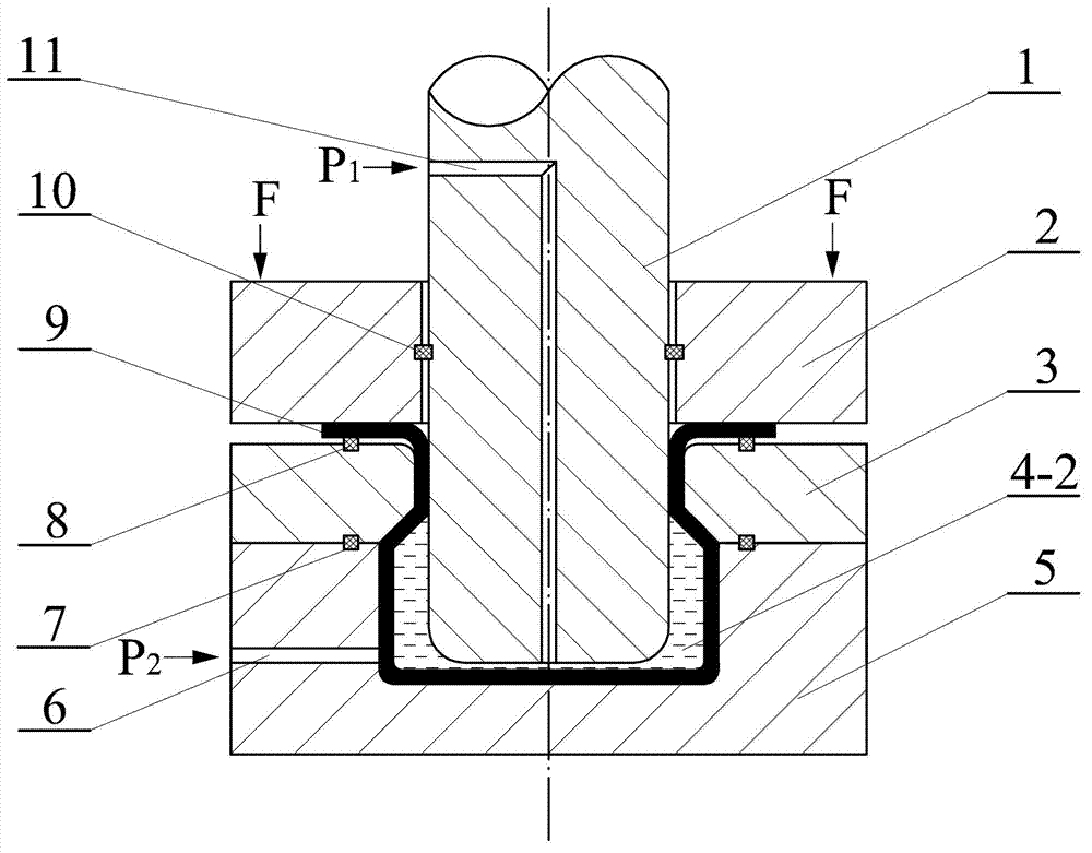
[0018] Specific implementation mode two: the following combination Figure 4 , Figure 5 This embodiment will be specifically described. The difference between this embodiment and the first embodiment is that the angle of the diameter-reducing step at the upper die 3 is 30°, and the other components are the same as the first embodiment.

specific Embodiment approach 3

[0019] Specific implementation mode three: the following combination Figure 6 , Figure 7 This embodiment will be specifically described. The difference between this embodiment and specific embodiment 1 is that the forming cylindrical part is a tapered cylinder whose outer diameter increases linearly from top to bottom, and the lower die 5 and the upper die 3 form a complete tapered die, wherein The upper die 3 is provided with a medium injection hole, and other components and structures are the same as those in the first embodiment.


PUM


Abstract

A hydraulic forming device and method of a reducing cylindrical part relate to a hydraulic forming device and method of a metal plate. Aiming at the bottleneck problems of high cost, long cycle and poor forming property in a roll welding process used due to the fact that the reducing cylindrical part, the section of an axis part of which is of a bottle shape with a small upper part and a big lower part, is difficult to machine by using the traditional plate hydraulic forming method, the device comprises a lower concave die and an upper concave die; a blank holder and a convex die are arranged above the upper concave die; the shape of a cavity in the concave die is in accordance with the shape of the outer outline of a finally-formed cylindrical part, namely the cavity is configured into a reducing cylinder with the aperture gradually reduced from the bottom to the top or reducing in a stepped form; and the lower concave die and the convex die are respectively provided with an injection hole. The forming method sequentially comprises the following steps of: injecting medium in the cavity, arranging blanks, pressing the blanks, applying backpressure, downwards moving the convex die, and pressing in the inner cavity of a pre-formed part in order to close to the die. The blanks are under the action of a pressure difference of inner and outer dynamic fluids in the forming process due to the injection holes arranged in the convex die, the die-close forming of the blanks is finished at one step, and the formed part can be smoothly taken out due to the design of the combined concave die.

Description

technical field [0001] The present invention relates to a hydroforming device and method for sheet metal, in particular to a hydraulic device and method for forming a diameter-reducing cylindrical part, and in particular to a device whose outer diameter gradually decreases from the bottom up or decreases in steps. A hydroforming device and method for a variable-diameter tubular member. Background technique [0002] In order to achieve energy saving and emission reduction, the significance of lightweight design is increasingly highlighted. There are two ways to achieve lightweight: material lightweight and structural lightweight. Sheet metal hydroforming technology uses liquid water or oil as the force transmission medium to replace the traditional rigid punch or die, so that the blank is formed by fitting the die or punch under the pressure of the force transmission medium. Hydroforming technology can overcome the shortcomings of traditional processes in sheet or pipe form...

Claims


Application Information

Patent Timeline
Patent Type & Authority Applications(China)
IPC IPC(8): B21D26/021B21D26/031B21D26/029
Inventor 林俊峰李峰张鑫龙
Owner HARBIN INST OF TECH
Why Eureka
Try Eureka