Cutter damage and abrasion state detecting method and cutter damage and abrasion state detecting system

A wear state and detection method technology, which is applied in manufacturing tools, measuring/indicating equipment, metal processing machinery parts, etc., can solve the problems of complex, difficult to accurately judge tool wear and tear state, and many interference factors.

Active Publication Date: 2012-11-07
CHANGZHOU XIAOGUO INFORMATION SERVICES
View PDF4 Cites 50 Cited by
  • Summary
  • Abstract
  • Description
  • Claims
  • Application Information

AI Technical Summary

Problems solved by technology

[0004] The technical problem to be solved by the present invention is: to overcome the deficiencies in the prior art, the method of indirect detection of tool damage and wear has many and complicated interference factors, and it is not easy to accurately determine the state of tool damage and wear. The state detection method and its detection system detect and judge the damage and wear state of the tool in real time through the vibration generated by the tool during cutting and grinding

Method used


Image

  • Cutter damage and abrasion state detecting method and cutter damage and abrasion state detecting system
  • Cutter damage and abrasion state detecting method and cutter damage and abrasion state detecting system
  • Cutter damage and abrasion state detecting method and cutter damage and abrasion state detecting system

Examples


Embodiment Construction

[0051] The present invention is described in further detail now in conjunction with accompanying drawing. These drawings are all simplified schematic diagrams, which only illustrate the basic structure of the present invention in a schematic manner, so they only show the configurations related to the present invention.

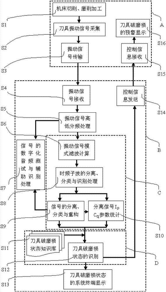
[0052] The tool damage detection method of the present invention includes the following steps:

[0053] ①Measure the vibration signal during tool cutting and grinding, and collect, amplify, transmit and display the vibration signal;

[0054] ②Calculate the vibration signal with the mode filtering method to realize the optimal decomposition and processing of the vibration signal;

[0055] ③ Classify and sort out the time-frequency wavelet of the vibration signal and extract the feature, separate the operation signal of the mechanical equipment, and obtain the cutting and grinding signal in the vibration signal of the tool, and the classification signal of the ...


PUM


Abstract

The invention relates to a cutter damage and abrasion state detecting method, which comprises the following steps that 1, vibration signals in the cutter cutting and grinding processes are measured; 2, the vibration signals are subjected to mode filtering calculation; 3, time-frequency wavelets of the vibration signals are subjected to classification sorting and feature extractions; and 4, the time-frequency wavelets are subjected to classification, collection and signal separation processing, various kinds of time-frequency wavelets are subjected to signal reconstruction, the kurtosis index (Cq) and the peak index (Ip) of various kinds of signals are then counted, the cutter damage and abrasion state and the machine tool operation state are detected under the dynamic distribution condition of a Cq-Iq plane according to various kinds of separation signal index parameters, and the identification detection and the quantitative early warning and forecast of the cutter damage and abrasion state are realized. Through single monitoring equipment, the detection of the cutter damage and abrasion state is realized, the signal identification stability is good, the mechanical processing production safety is ensured, the precision of processing parts is improved, and the production rate and the utilization rate of a machine tool are improved.

Description

technical field [0001] The invention relates to the fields of tool wear monitoring, diagnosis and maintenance in machining, in particular to a tool wear state detection method and a detection system thereof. Background technique [0002] Industrial statistics show that tool failure is the primary factor causing machine tool failures, and the resulting downtime accounts for 1 / 5 to 1 / 3 of the total downtime of CNC machine tools. Studies have shown that CNC machine tools equipped with a tool monitoring system can reduce downtime by 75%, increase productivity by 10% to 60%, increase machine tool utilization by more than 50%, and save processing costs by 30%. [0003] At present, a lot of research has been carried out on the detection of tool breakage and wear at home and abroad. Major companies in Germany, the United States, Japan, Italy and Sweden have also developed their own tool breakage and wear detectors. There are two main categories of tool damage detection methods: dir...

Claims


Application Information

Patent Timeline
Patent Type & Authority Applications(China)
IPC IPC(8): B23Q17/09
Inventor 吕苗荣陆健
Owner CHANGZHOU XIAOGUO INFORMATION SERVICES
Why Eureka
Try Eureka