Concrete mixer

A technology for concrete mixer trucks and mixing tanks, which is applied to cement mixing devices, clay preparation devices, chemical instruments and methods, etc., and can solve the problem of the center of gravity deviation of the upper part of the concrete mixer truck, affecting the life and safety of the whole vehicle, and affecting driving comfort issues

Inactive Publication Date: 2012-11-07
BEIQI FOTON MOTOR CO LTD
View PDF7 Cites 14 Cited by
  • Summary
  • Abstract
  • Description
  • Claims
  • Application Information

AI Technical Summary

Problems solved by technology

[0004] However, when the above-mentioned concrete mixer truck is working, in order to ensure the quality of the concrete and prevent the concrete from solidifying, the mixing tank cannot stop rotating during the working process, and the concrete is semi-fluid, and the movement state of the concrete is complicated and unstable when the mixing tank is rotating. Make the center of gravity of the upper part of the concrete mixer truck easy to shift
In addition, when the concrete mixer truck is moving, especially when braking or going up and down, the concrete in the mixing tank will generate a large impact and vibration, which will be transmitted to the sub-beam and the chassis of the car through the front bracket and the rear bracket. The main beam affects the life and safety of the vehicle, and at the same time affects the driving comfort

Method used


Image

  • Concrete mixer
  • Concrete mixer
  • Concrete mixer

Examples


Embodiment Construction

[0021] In order to further explain the technical means and effects of the present invention to achieve the intended purpose of the invention, the specific implementation, structure, characteristics and effects of the concrete mixer truck proposed according to the present invention will be described below in conjunction with the accompanying drawings and preferred embodiments. The details are as follows.

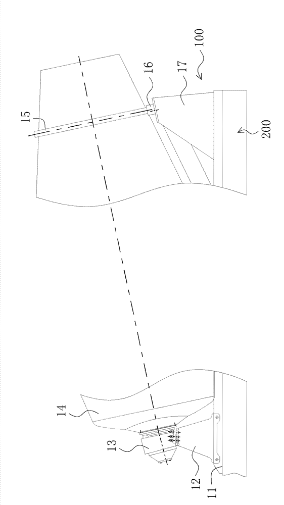
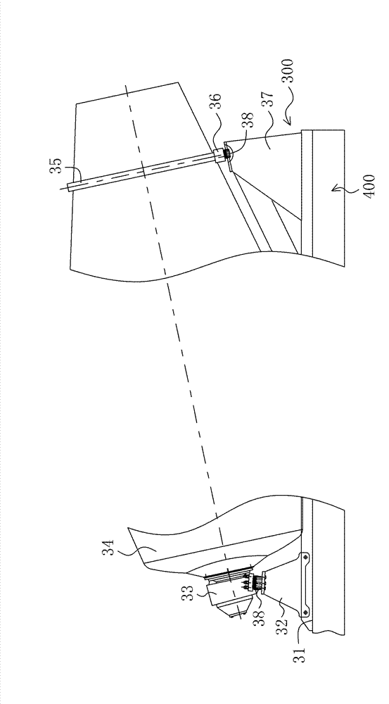
[0022] The concrete mixer truck of the present invention includes an upper part 300 and a car chassis 400, and the upper part 300 is fixed to the car chassis 400 for providing the mixed concrete. figure 2 Shown is a schematic diagram of an embodiment of the upper body part of the concrete mixer truck of the present invention. Such as figure 2 As shown, the upper part 300 includes a subframe 31 , a front bracket 32 ​​, a speed reducer 33 , a mixing tank 34 , a guide rail 35 , a supporting wheel 36 , a rear bracket 37 and a plurality of elastic damping devices 38 . Wherein,...


PUM


Abstract

The invention discloses a concrete mixer, which comprises a chassis and an upper part. The upper part comprises a decelerator, an agitator tank, a guide rail, a support roller and at least an elastic damping device. The decelerator, which is arranged on the chassis and is connected with one end of the agitator tank, is used for driving the agitator tank to rotate. The guide rail is arranged at the other end of the agitator tank, and a part of the guide rail contacts with the support roller so as to make the support roller support the agitator tank to rotate. The at least one elastic damping device, which is arranged between the decelerator and the chassis or/and between the support roller and the chassis, comprises a pedestal, a spring and a connection gasket. The pedestal is connected with the chassis. The connection gasket is connected with the decelerator or the support roller. The spring is positioned between the pedestal and the connection gasket, thus effectively buffering impact force and vibration of concrete in the agitator tank.

Description

technical field [0001] The invention relates to a concrete mixing and transporting machine, in particular to a concrete mixer truck. Background technique [0002] figure 1 Shown is a schematic diagram of the upper part of an existing concrete mixer truck. Such as figure 1 As shown, the upper part 100 of the existing concrete mixer truck includes a subbeam 11 , a front bracket 12 , a speed reducer 13 , a mixing tank 14 , a guide rail 15 , supporting wheels 16 and a rear bracket 17 . Among them, the sub-beam 11 is fastened to the main beam of the automobile chassis 200 through connectors, the front bracket 12 and the rear bracket 17 are respectively fastened to the front and rear ends of the sub-beam 11, and the base of the reducer 13 is fixed to the front by a plurality of high-strength bolts. On the bracket 12, the output flange of the reducer 13 is connected to the front end of the mixing tank 14 through bolts, and the rear end of the mixing tank 14 is placed on two supp...

Claims


Application Information

Patent Timeline
Patent Type & Authority Applications(China)
IPC IPC(8): B28C5/42
CPCB28C5/4265B28C5/4217
Inventor 赵彦田娟韩术亭
Owner BEIQI FOTON MOTOR CO LTD
Why Eureka
Try Eureka