Pneumatic-tyre wheel

A technology for pneumatic tires and tires, which is applied to tire parts, tire tread/tread pattern, rolling resistance optimization, etc., can solve the problem of low hysteresis loss, etc., to reduce rolling resistance, small hysteresis loss, and reduce rolling resistance Effect

Inactive Publication Date: 2012-11-07
SUMITOMO RUBBER IND LTD
View PDF8 Cites 10 Cited by
  • Summary
  • Abstract
  • Description
  • Claims
  • Application Information

AI Technical Summary

Problems solved by technology

[0003] However, in the pneumatic tire provided with the above-mentioned grooves, since the air layer near the outer surface of the sidewall part is stirred by the rolling of the tire, the rubber of the sidewall part is cooled, so there is little effect of reducing hysteresis loss. The problem

Method used


Image

  • Pneumatic-tyre wheel
  • Pneumatic-tyre wheel
  • Pneumatic-tyre wheel

Examples


Embodiment

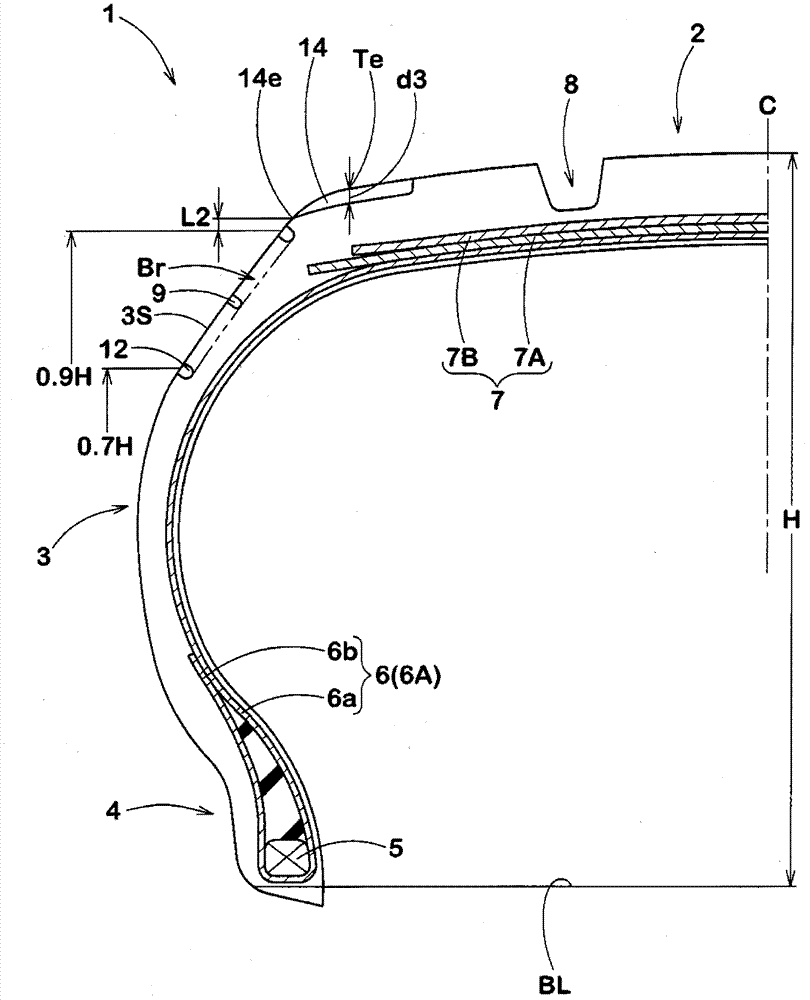
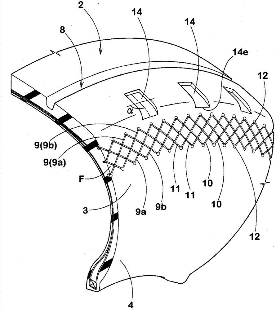
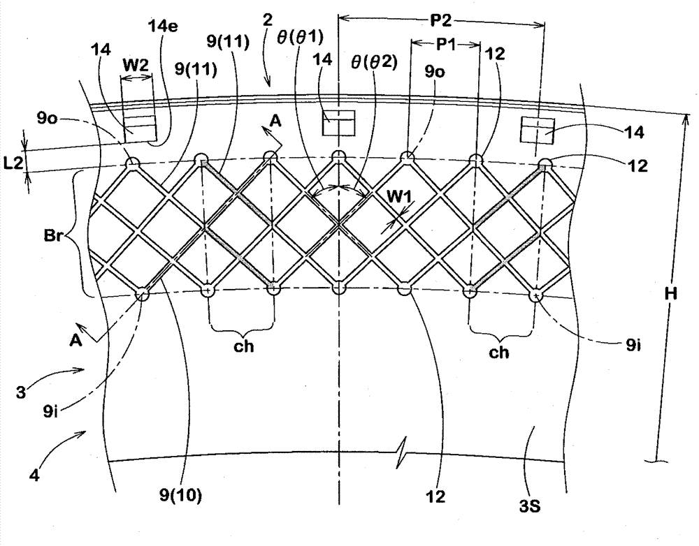
[0044] Manufacturing has figure 1 The basic structure and figure 2 Pneumatic tires (size: 175 / 65R15) with the shape of the sidewall shown and the sipe of the specifications in Table 1 were tested, and their performance was tested. Among them, the common specifications are as follows.

[0045] Tread width: 148mm

[0046] Sipe width W1: 0.5mm

[0047] Tire radial angle of sipe θ: 45 degrees

[0048] Hole: The inner end and outer end of each sipe in the tire radial direction are provided in a perfect circle.

[0049] The depth of the hole d2: 3.0mm

[0050] The test method is as follows.

[0051]

[0052] A rolling resistance tester was used to measure the rolling resistance when the rim was mounted on the above-mentioned pneumatic tire and running on a roller having a diameter of 1.7 m under the following conditions. The result is expressed by an index of 100 in Comparative Example 1, and the smaller the value, the better.

[0053] Rim size: 14×5JJ

[0054] Internal pressure: 230kPa

[0055...


PUM


Abstract

In a pneumatic-tyre wheel, through restricting shapes and allocation positions of sipes, the rolling resistance is reduced. Spipes (9) are arranged at intervals along the tyre circumference on the outer surface (3S) of a tyre side part (3) of at least one part of a pneumatic-tyre wheel (1). Under the unloaded normal state that a rim is assembled inside a regular rim and is filled with standard internal pressure, the sipes (9) are arranged in a tyre wall area which is 70-90% of tyre cross section height (H)away from a tyre bead reference line (BL), and is inclinedly extended in 40-50 degrees in relative to the tyre radiating direction, the sipe width (W1) is 0.5 to 1.0mm, and the adjacent sipes of the tyre circumference are provided with at least parts of overlapping parts (ch) which are mutually overlapped on the tyre circumference.

Description

Technical field [0001] The present invention relates to a pneumatic tire with reduced rolling resistance. Background technique [0002] In recent years, in order to improve the fuel efficiency of vehicles, it is desired to reduce the rolling resistance of pneumatic tires. As a method of reducing rolling resistance, for example, the following Patent Document 1 discloses that a wider groove is provided on the outer surface of the sidewall portion to suppress the rubber deformation of the sidewall portion caused by the rolling of the tire, thereby reducing hysteresis loss Methods. Among them, the hysteresis loss tends to decrease if the temperature of the rubber increases, and conversely increase if the temperature of the rubber decreases. [0003] However, in a pneumatic tire provided with the above-mentioned grooves, the air layer near the outer surface of the sidewall portion is stirred by the rolling of the tire, so that the rubber of the sidewall portion is cooled, so there is ...

Claims


Application Information

Patent Timeline
Patent Type & Authority Applications(China)
IPC IPC(8): B60C11/01
CPCY02T10/86
Inventor 久保田康弘
Owner SUMITOMO RUBBER IND LTD
Why Eureka
Try Eureka