
Dynamic reactive compensation system based on magnetic control electric reactor

A magnetically controlled reactor and compensation system technology, applied in reactive power compensation, reactive power adjustment/elimination/compensation, AC network to reduce harmonics/ripples, etc., can solve frequent operation, transformer capacity limitation, occupation Large land area and other problems, to reduce line loss, adjust network voltage, improve the effect of use efficiency

Inactive Publication Date: 2012-12-05
青岛海电电气有限公司
View PDF4 Cites 7 Cited by
  • Summary
  • Abstract
  • Description
  • Claims
  • Application Information

AI Technical Summary

Problems solved by technology

The switch (circuit breaker) switching capacitor and reactor group adjustment method is discrete, and can only be switched in groups, and is limited by the capacity of the transformer, so it cannot be frequently operated and the ideal compensation effect can be achieved.
The inrush current and overvoltage caused by switching capacitors are very harmful to the system and the equipment itself
The existing phase-controlled reactor dynamic compensation device is not only expensive, but also occupies a large area, has a complex structure, and has low reliability

Method used


Image

  • Dynamic reactive compensation system based on magnetic control electric reactor
  • Dynamic reactive compensation system based on magnetic control electric reactor
  • Dynamic reactive compensation system based on magnetic control electric reactor

Examples


Embodiment Construction

[0023] The present invention is described in detail below with reference to the accompanying drawings:

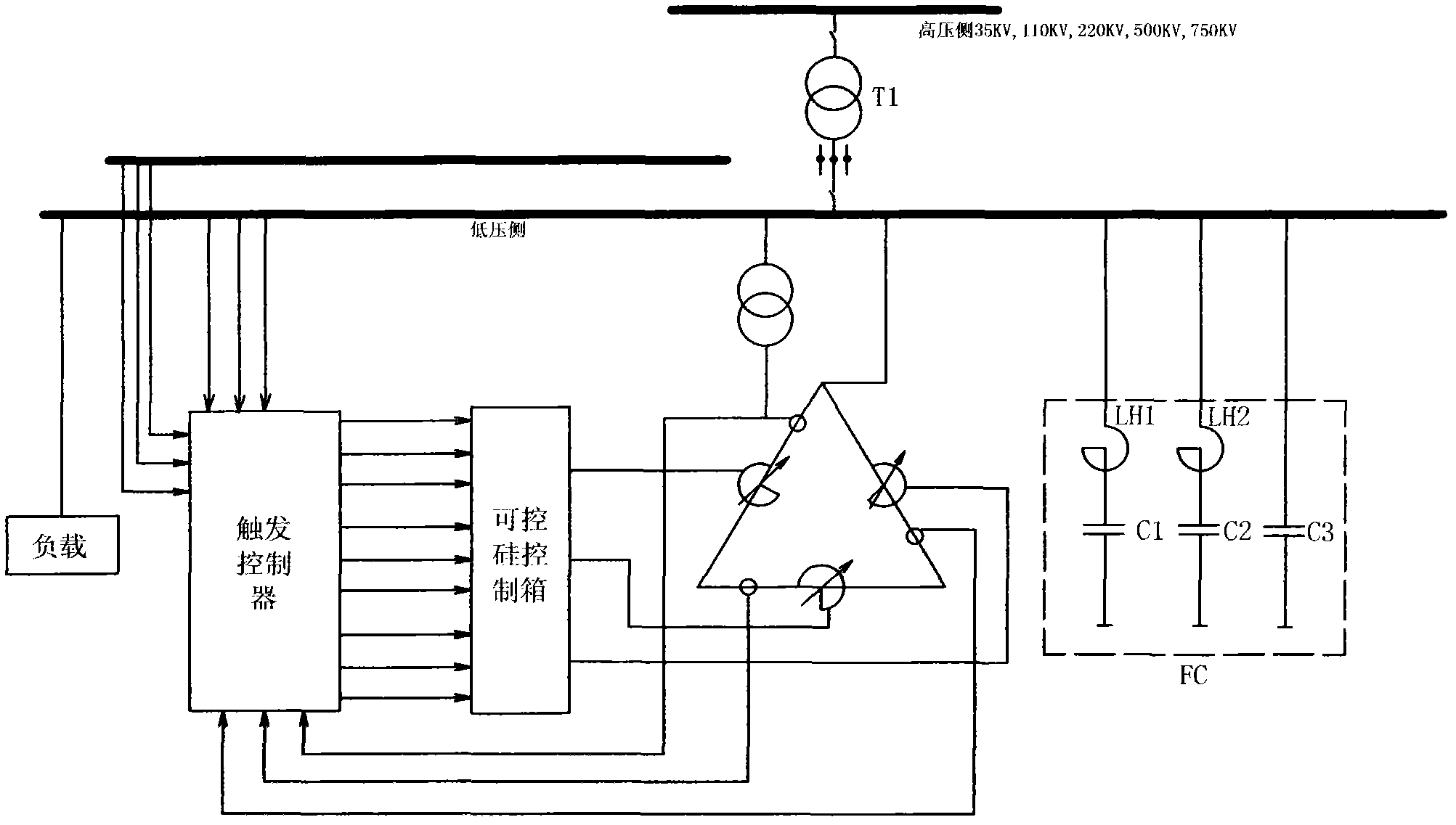
[0024] A dynamic reactive power compensation system based on a magnetron reactor, the system includes a passive filter FC for reactive power compensation and harmonic filtering and a magnetic Control reactor MCR;

[0025] The passive filter FC is provided with a filter reactor and a filter capacitor connected to the electrical equipment line; the passive filter FC includes a reactor LH1, LH2 and capacitors C1, C2, capacitor C3 arranged on the neutral line.

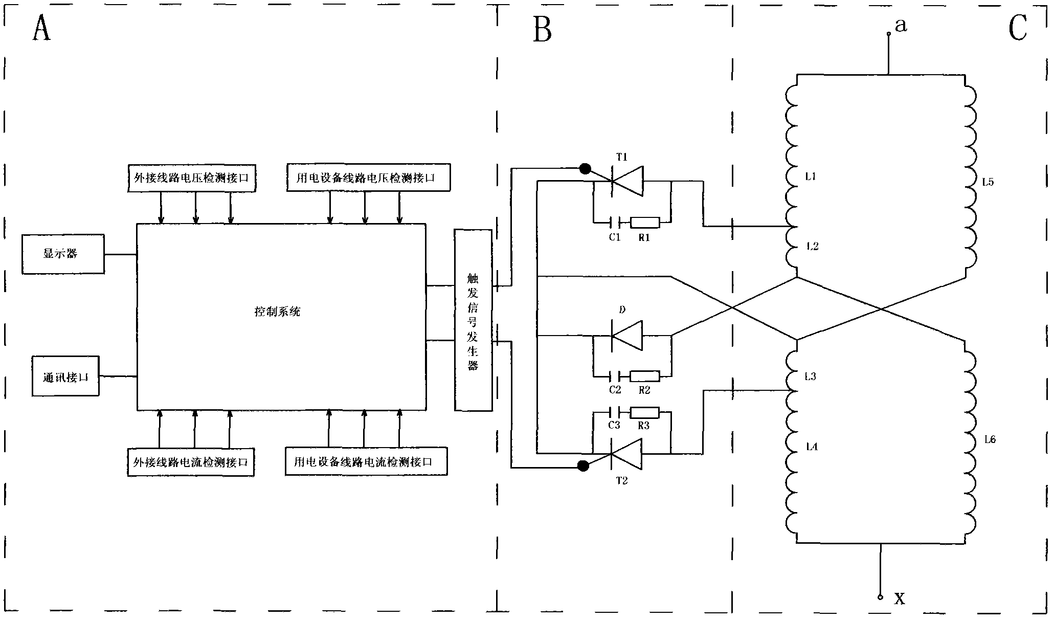
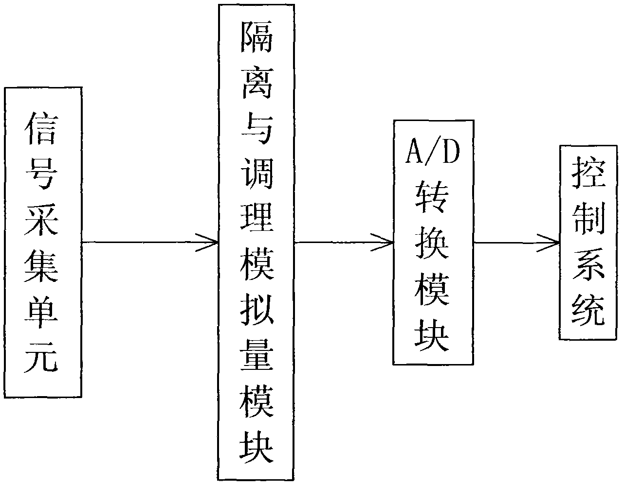
[0026] The magnetic control reactor MCR is a three-phase magnetic control reactor, including a reactor winding C, a rectifier thyristor controller B and a trigger controller A; each phase electric controller winding is composed of L1-L6, and the rectification is controllable Silicon controller B is composed of thyristor T1, T2, diode D, capacitors C1, C2, C3, resistors R1, R2, R3, trigger controller A is composed of c...


PUM


Abstract

The invention relates to a dynamic reactive compensation system based on a magnetic control electric reactor. The dynamic reactive compensation system comprises a passive filter FC and an MCR (Magnetic Control Reactor), wherein the passive filter FC is used for reactive compensation and harmonic filter, the MCR is used for balancing an inductive load. The dynamic reactive compensation system disclosed by the invention has the advantages that the reliability if high, 20-year basic maintenance-free running can be realized, and the maintaining and repairing cost can be reduced to a large extent; the response ability is quick, and the response speed can be up to 20ms; the regulating range is large, and the regulating range in more than 100 times can be reached; the occupied area is small, the installation is convenient, and a device can be naturally cooled by adopting an oil immersion mode; the harmonic wave is small and has no pollution to a power grid and has no any bad influence on a capacitor group, and the traditional device is conveniently utilized in a reform occasion; the overload ability is strong, 30-second 100% overload and half-hour 40% overload can be realized; the consumption is less, the MCR is in large capacity, the consumption is less than 0.5%, and in a common system, only 0.8%-1.5% of the consumption can be realized; the overvoltage ability is strong, the voltage limiting ability is good, and the dynamic reactive compensation system has a natural automatic voltage limiting ability; and no electromagnetic pollution works on the environment and the human body.

Description

technical field [0001] The invention relates to the field of energy-saving control of power grids and power transmission and transformation equipment, in particular to a reactive power compensation system based on a magnetic control reactor for high-voltage dynamic controllable reactive power compensation. Background technique [0002] At present, the main devices for reactive power compensation are capacitors, reactors and a small amount of dynamic reactive power compensation devices. Switching (circuit breaker) capacitors and reactors are adjusted discretely, and can only be switched in groups, and limited by the capacity of the transformer, frequent operations and ideal compensation effects cannot be achieved. Inrush currents and overvoltages caused by switching switched capacitors are very harmful to the system and the equipment itself. The existing phase-controlled reactor dynamic compensation device is not only expensive, but also occupies a large area, has a complica...

Claims


Application Information

Patent Timeline
Patent Type & Authority Applications(China)
IPC IPC(8): H02J3/18H02J3/01
CPCY02E40/30Y02E40/40
Inventor 曹修亭
Owner 青岛海电电气有限公司
Learn More