High-speed permanent magnet synchronous motor and assembly method thereof

A technology of permanent magnet synchronous motor and assembly method, which is applied to synchronous motors with static armatures and rotating magnets, electromechanical devices, and manufacturing motor generators, etc. Adjustment space is limited and other problems, to achieve the effect of reducing eddy current loss and hysteresis loss, avoiding the problem of rotor magnetic saturation, and reducing radial size

Inactive Publication Date: 2013-05-22
HUNAN UNIV
View PDF7 Cites 8 Cited by
  • Summary
  • Abstract
  • Description
  • Claims
  • Application Information

AI Technical Summary

Problems solved by technology

Under the constraints of large inner hole and small outer diameter of the rotor, the electromagnetic design of the motor rotor is very difficult, and the space for adjustment is very limited.
If the power density of the designed motor is too large, magnetic saturation is likely to occur, resulting in a decrease in motor performance; if the axial length of the rotor is increased to increase the power, the span of the main shaft will increase, and the critical speed of the main shaft system will decrease, which is not conducive to the realization of high speed.

Method used


Image

  • High-speed permanent magnet synchronous motor and assembly method thereof
  • High-speed permanent magnet synchronous motor and assembly method thereof

Examples


Embodiment Construction

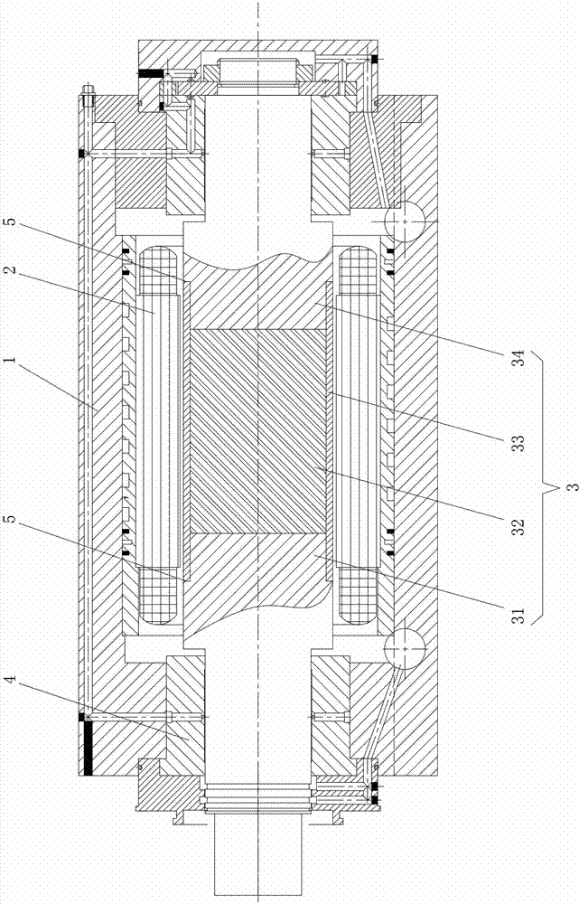
[0027] figure 1 It shows an embodiment of a high-speed permanent magnet synchronous motor of the present invention, the high-speed permanent magnet synchronous motor includes a motor housing 1, a motor stator 2, a main shaft rotor assembly 3 and a pair of The bearing assembly 4, the motor stator 2 is fixed in the motor housing 1, the main shaft rotor assembly 3 is set in the motor stator 2, the two ends of the main shaft rotor assembly 3 are supported on the motor housing 1 through the bearing assembly 4, the main shaft rotor Assembly 3 includes rotor front half shaft 31, rotor permanent magnet 32, rotor sleeve 33 and rotor rear half shaft 34, rotor permanent magnet 32 ​​is set in rotor sleeve 33, one end of rotor sleeve 33 is fixedly connected to rotor front half shaft 31, and the other One end is fixedly connected to the rear half shaft 34 of the rotor, and the rotor permanent magnet 32 ​​is integrated with the main shaft of the motor, and is packaged inside the main shaft, ...


PUM


Abstract

Disclosed are a high-speed permanent magnet synchronous motor and an assembly method thereof. The motor comprises a motor shell, a motor stator, a spindle rotor component and a pair of bearing assemblies, the bearing assemblies are separately arranged at the front end and the rear end of the shell, the motor stator is fixed into the motor shell, the spindle rotor component is sleeved in the motor stator, two ends of the spindle rotor component are supported on the motor shell through the bearing assemblies, the spindle rotor component comprises a front rotor half shaft, a rotor permanent magnet, a rotor sleeve and a rear rotor half shaft, the rotor permanent magnet is sleeved in the rotor sleeve, one end of the rotor sleeve is fixedly connected with the front rotor half shaft, and the other end of the rotor sleeve is fixedly connected with the rear rotor half shaft. The high-speed permanent magnet synchronous motor is compact in structure, sufficient in space usage, small in radial dimension and particularly suitable for meeting the requirement on high rotation speed. The assembly method includes the steps: 1) mounting the motor stator into the motor shell; 2) assembling the spindle rotor component and magnetizing the rotor permanent magnet in the spindle rotor component after the spindle rotor component is assembled; and 3) mounting the spindle rotor component into the motor stator, and supporting the spindle rotor component on the motor shell through the bearing assemblies.

Description

technical field [0001] The invention relates to motor equipment, in particular to a high-speed permanent magnet synchronous motor and an assembly method thereof. Background technique [0002] Due to its compact structure, high power density, high working efficiency, and remarkable benefits in energy saving and consumption reduction, permanent magnet synchronous motors have been widely used in fields such as motors and generators. In recent years, in the industrial field, the demand for equipment that uses permanent magnet synchronous motors to directly drive loads has become more and more urgent, such as air compressors that directly drive impellers with permanent magnet motors, and CNC machine tool spindles that directly drive grinding wheels or tools with permanent magnet motors , high-speed turbine generators that directly drive permanent magnet motors to generate electricity with turbines, etc. The wide application of these permanent magnet motor direct drive devices wi...

Claims


Application Information

Patent Timeline
Patent Type & Authority Applications(China)
IPC IPC(8): H02K21/14H02K1/27H02K15/00
Inventor 熊万里吕浪蒋旭光
Owner HUNAN UNIV
Why Eureka
Try Eureka