Device for unfolding surface of space rope system

A space tether and unfolding surface technology, applied in the aerospace field, can solve the problems of not considering stability and control, stable deployment and stable work, and inability to deploy structures, so as to achieve effective forming, reduce complexity, and reduce surface density Effect

Inactive Publication Date: 2012-11-07
XIDIAN UNIV
View PDF7 Cites 11 Cited by
  • Summary
  • Abstract
  • Description
  • Claims
  • Application Information

AI Technical Summary

Problems solved by technology

However, in this invention, its stability and control issues are not considered, that is, how to realize the effective shaping of its structure in space and the independent stability of the orbit and attitude of the entire satellite system, resulting in the inability of the deployable structure to be stably deployed and work smoothly in space. Defects

Method used


Image

  • Device for unfolding surface of space rope system
  • Device for unfolding surface of space rope system
  • Device for unfolding surface of space rope system

Examples


Embodiment 1

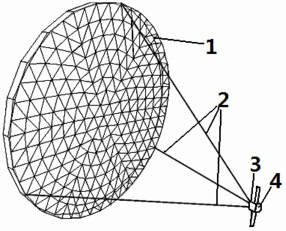
[0033] refer to figure 1 , the present invention includes a reflective surface 1, a flexible traction cable 2 and a traction cable control mechanism 3 located on a satellite platform 4. in:

[0034] The number N of reflective surfaces or transmissive surfaces, its value range is 1≤N≤9, when it is a transmissive surface, its value is determined according to the design requirements of large telescopes or large solar concentrators, when it is a reflective surface, N =1, so the number of reflecting surfaces in this example is N=1. The reflective surface structure adopts an open-hole fixed truss structure, which consists of Figure 4 The ring connecting joint 5 and the folding ring 4 shown are formed, and every two folding rings 4 are connected by a ring connecting joint 5, both of which are plural, and the specific number is determined according to the diameter of the unfolded curved surface.

[0035] The structure of ring connection joint 5 is as follows Figure 8 (a) and F...

Embodiment 2

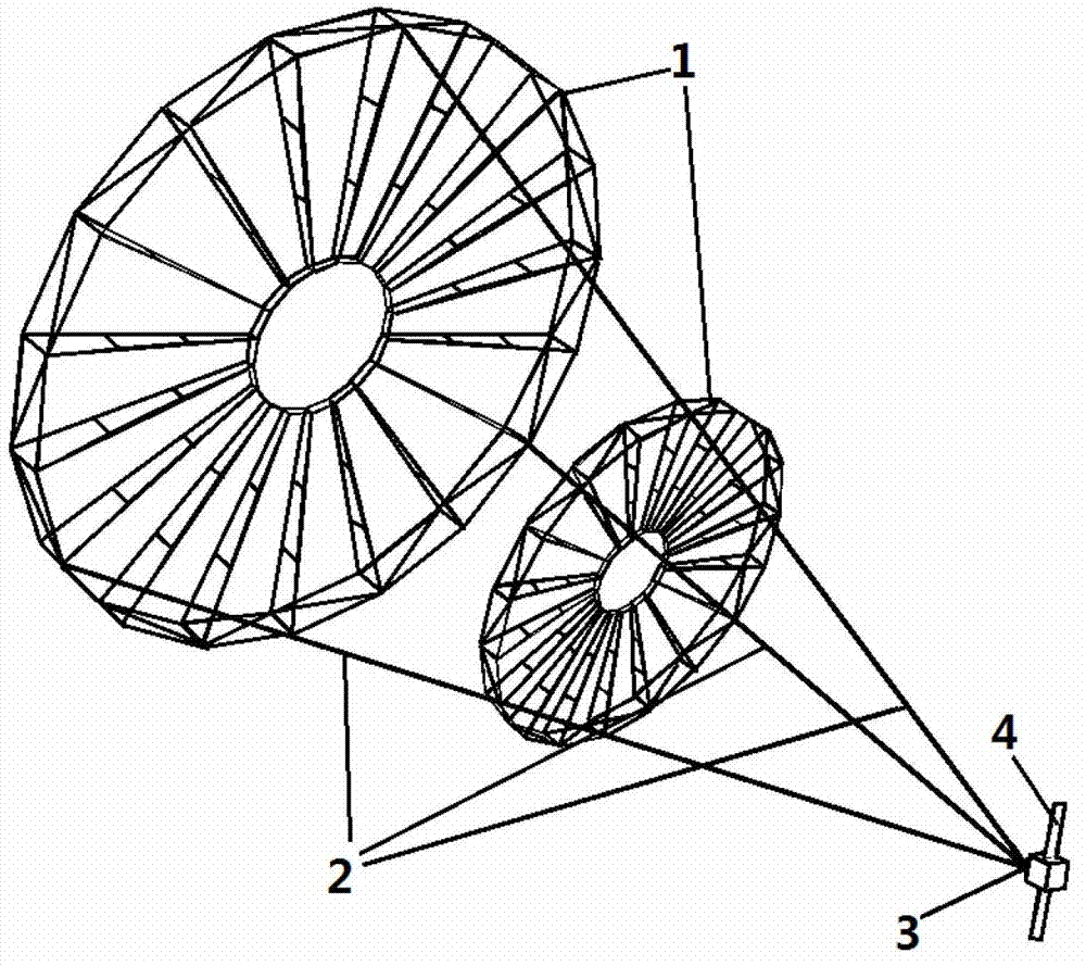
[0047] refer to figure 2 , the present invention includes transmission surfaces 1 with different diameters, flexible traction cables 2 and a traction cable control mechanism 3 located on a satellite platform 4 . in:

[0048] The number N of reflective or transmissive surfaces, its value range is 1≤N≤9, when it is a reflective surface, N=1, when it is a transmissive surface, its value is based on the design of large telescopes or large solar concentrators The requirements are determined. According to the requirements, take two transmission surfaces.

[0049] The transmission surface structure adopts an open-hole fixed truss structure, which consists of Figure 4 The ring connecting joint 5 and the folding ring 4 shown are formed, and every two folding rings 4 are connected by a ring connecting joint 5, both of which are plural, and the specific number is determined according to the diameter of the unfolded curved surface.

[0050] The structure of ring connection joint 5 is...


PUM


Abstract

The invention discloses a device for unfolding a surface of a space rope system, and is mainly used for solving the problems that the prior art is difficult to mold and has bad stability. The device comprises a plurality of reflectors or transmission surfaces (1), a plurality of flexible pulling cables (2), a satellite platform (4) and a plurality of control mechanisms (3) of the pulling cables, wherein each reflector or transmission surface (1) is composed of a folding ring (4) and a ring connecting joint (5), and is stacked according to the caliber size; one end of each flexible pulling cable (2) penetrates through a corresponding hole of the folding ring (4) of the reflector or transmission surface with the biggest caliber to be tied fixedly, and then penetrates through the folding ring (4) of the other reflector or transmission surface to be tied fixedly; the other end of each flexible pulling cable (2) is connected with the control mechanisms (3) on the satellite platform; and the reflectors or transmission surfaces are connected hierarchically to form a stacked structure composed of the satellite platform and all reflectors or transmission surfaces so as to form a space rope system. The device can achieve effective molding structure, autonomous orbit and pose stability of the whole system, so that the device can be applied in a large antenna or telescope in space.

Description

technical field [0001] The invention belongs to the field of aerospace technology, in particular to an expandable surface device connected by rope traction in space, which can be used for large reflective surfaces or lens antennas, large telescopes, and large solar energy concentrators in space. Background technique [0002] With the continuous enhancement of human space carrying capacity and the continuous development of aerospace technology, space large-scale deployable devices such as large-scale deployable antennas and large-scale solar panels have been used more and more. Space large-scale deployable antennas have been used in space communications. The field has produced huge economic and social benefits. Large and super-large expandable structures in space also have attractive application prospects in other fields, such as space solar reflectors, solar orbit stations, space elevators, space orbit shifters, etc., and even become one of the key components for the success...

Claims


Application Information

Patent Timeline
Patent Type & Authority Applications(China)
IPC IPC(8): B64G1/24
Inventor 郑飞陈梅洪学飞
Owner XIDIAN UNIV
Why Eureka
Try Eureka