
Assembled-type externally-restricted buckling-restrained supporting component

An anti-buckling support and assembled technology, which is applied in the direction of building components, earthquake resistance, etc., can solve problems such as inability to adjust, internal core material damage, and greater impact on manufacturing accuracy, so as to avoid overall disassembly and overall replacement, and facilitate maintenance and replacement. Avoid the effect of imprecise gap size control

Inactive Publication Date: 2012-11-07
HOHAI UNIV
View PDF6 Cites 12 Cited by
  • Summary
  • Abstract
  • Description
  • Claims
  • Application Information

AI Technical Summary

Problems solved by technology

[0003] There are many cross-sectional shapes and composition methods commonly used at present, but there are the following problems: (1) The core materials of cross-shaped, straight-shaped and I-shaped cross-sections are formed by welding, resulting in excessive residual stress and reducing the energy dissipation capacity of buckling-resistant braces ; (2) The core material in the form of non-closed cross-section can bear limited yield load, which is difficult to meet the engineering requirements; (3) The gap between the outer restraint and the core material is greatly affected by the precision of component fabrication and cannot be adjusted (4) It is inconvenient to detect and inspect whether the internal core material is damaged; (5) Once the outer casing of the anti-buckling support member is damaged, it needs to be replaced as a whole, which involves the connection, disassembly and reinstallation of the anti-buckling support and the main structure
However, in the existing anti-buckling support forms, the outer casing is mostly integral

Method used


Image

  • Assembled-type externally-restricted buckling-restrained supporting component
  • Assembled-type externally-restricted buckling-restrained supporting component
  • Assembled-type externally-restricted buckling-restrained supporting component

Examples


Embodiment Construction

[0021] The accompanying drawings disclose, without limitation, the structural schematic diagrams of the preferred embodiments involved in the present invention; the technical solution of the present invention will be described in detail below in conjunction with the accompanying drawings.

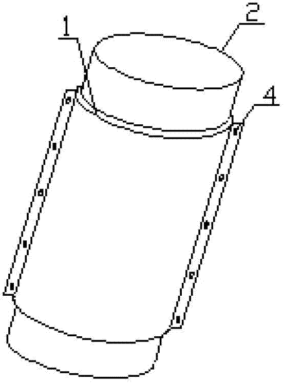
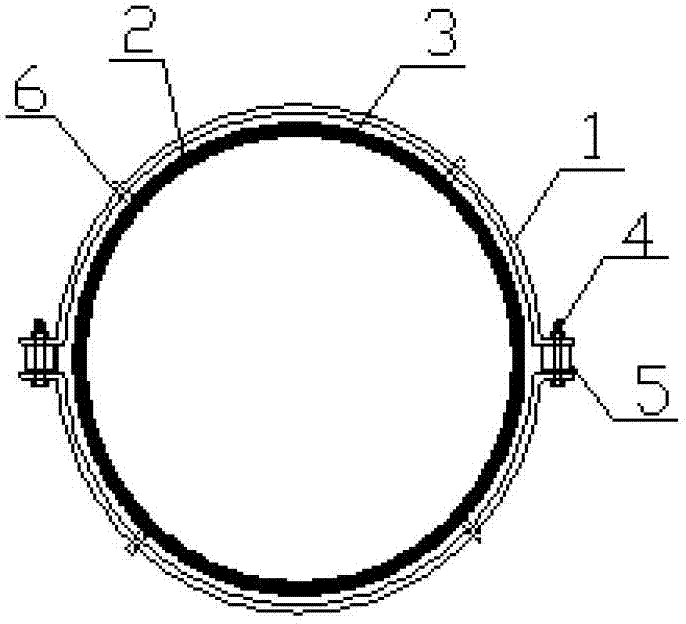
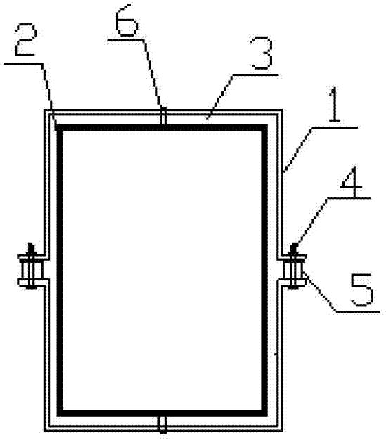
[0022] Such as Picture 1-1 , 1-2 As shown in , 2, the assembled external constraint buckling-resistant support member of the present invention includes an external constraint steel pipe and a core material steel pipe, an unbonded material layer is set between the external constraint steel pipe and the core material steel pipe, and the external constraint steel pipe Equally divided into two pieces of outer restraint steel pipe splits, the two outer restraint steel pipe splits are spliced ​​into one body through connecting bolts, and gaskets are arranged between the spliced ​​ends of the two outer restraint steel pipe splits; in addition, the outer restraint steel pipe splits The distance be...


PUM


Abstract

The invention discloses an assembled-type externally-restricted buckling-restrained supporting component, which comprises an externally-restricted steel pipe and a core-material steel pipe, wherein a non-cohesive material layer is arranged between the externally-restricted steel pipe and the core-material steel pipe, the externally-restricted steel pipe is equally arranged into two externally-restricted steel-pipe split bodies, the two externally-restricted steel-pipe split bodies are spliced into a whole through connecting bolts, and two gaskets are respectively arranged between the splicing ends of the two externally-restricted steel-pipe split bodies; and in addition, the space between the externally-restricted steel pipe and the core-material steel pipe is 1-2mm, and the thickness of the non-cohesive material layer is adapted to the space between the externally-restricted steel pipe and the core-material steel pipe. Therefore, under the condition of ensuring better earthquake-resisting and energy-consuming performances, in order to consider the convenient replacement and installment of the assembled-type externally-restricted buckling-restrained supporting component, the assembled-type externally-restricted steel pipe is adopted.

Description

technical field [0001] The invention relates to an anti-seismic energy-consuming component of an engineering structure, in particular to an assembled component with an outer restraint casing of an anti-buckling support, which belongs to the technical field of structural engineering. Background technique [0002] Buckling-resistant bracing is a new type of bracing that has been used in engineering structures in recent years, and it is also an efficient energy-dissipating shock-absorbing device (damper). It is composed of two parts without bonding material or gap provided between them. Under the action of wind load or earthquake, the supporting axial force in the buckling-resistant bracing frame is only borne by the steel supporting inner core, while the outer restraint member does not share its axial force in theory, but only through the lateral buckling deformation of the inner core. Constraints are used to prevent the overall buckling or local buckling failure of the suppo...

Claims


Application Information

Patent Timeline
IPC IPC(8): E04B1/98
Inventor 傅中秋吉伯海程苗
Owner HOHAI UNIV
Learn More