Exhaust gas condensate control method and exhaust gas recirculation system thereof

一种再循环系统、排放气体的技术,应用在废气再循环、电气控制、装料系统等方向,达到提高可用性和通用性、降低成本的效果

Active Publication Date: 2012-11-07
HYUNDAI MOTOR CO LTD +1
View PDF7 Cites 15 Cited by
  • Summary
  • Abstract
  • Description
  • Claims
  • Application Information

AI Technical Summary

Problems solved by technology

[0013] Unlike HP-EGR, for the LP-EGR type EGR system that is necessarily equipped with a turbocharger and an intercooler, the acceleration of corrosion in the turbocharger and intercooler is more serious, which may is a factor that greatly reduces the actual application of the LP-EGR type EGR system to the vehicle

Method used


Image

  • Exhaust gas condensate control method and exhaust gas recirculation system thereof
  • Exhaust gas condensate control method and exhaust gas recirculation system thereof
  • Exhaust gas condensate control method and exhaust gas recirculation system thereof

Examples


Embodiment Construction

[0046] Reference will now be made in detail to various embodiments of the invention, examples of which are illustrated in the accompanying drawings and described below. While the invention will be described in conjunction with exemplary embodiments, it will be appreciated that present description is not intended to limit the invention to those exemplary embodiments. On the contrary, the invention is intended to cover not only the exemplary embodiments but also various alternatives, modifications, equivalents and others which may be included within the spirit and scope of the invention as defined by the appended claims. implementation.

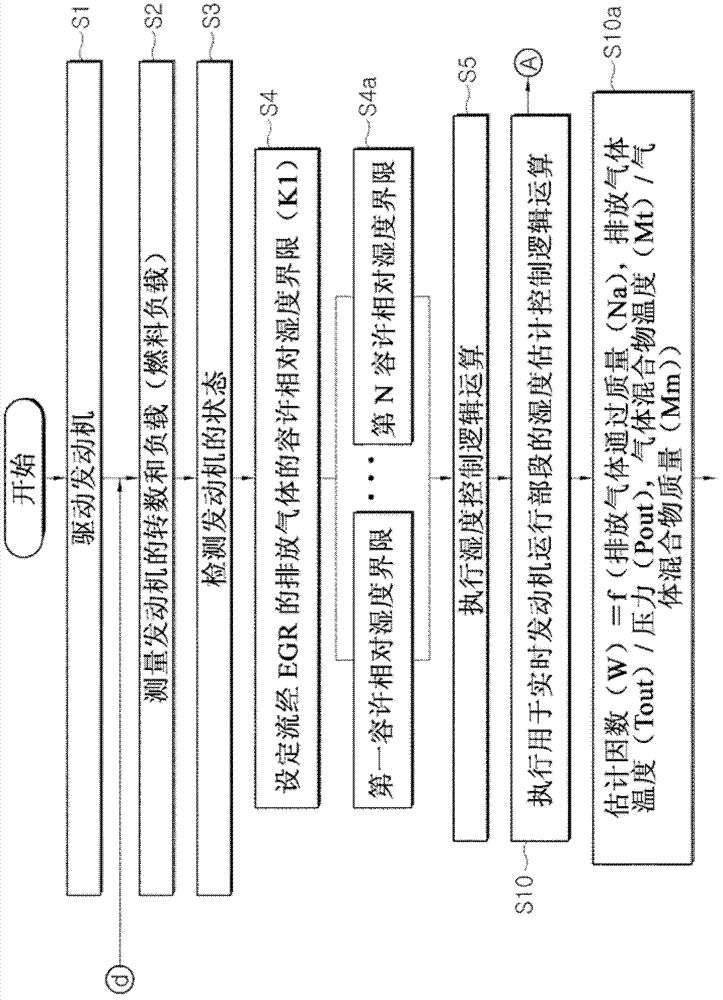
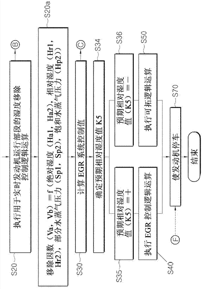
[0047] FIG. 1 , comprising FIG. 1(A) and FIG. 1(B), is a flow chart showing an exemplary method for treating condensate from exhaust gas flowing through an exhaust gas recirculation (EGR) system according to the present invention. Take control.

[0048] As shown in Figure 1, when the engine is started in step S1, the revolutions per minute (R...


PUM


Abstract

An exhaust gas condensate control method includes selecting modeling objects from the exhaust gas recirculation (EGR) system, acquiring control factors from the modeling objects, such as mass, temperature, pressure, absolute humidity, relative humidity, partial water vapor pressure of the exhaust gas and a gas mixture, calculating an estimated relative humidity value, a desired relative humidity value from estimated relative humidity value, and an allowable relative humidity limit and a current relative humidity value of the EGR system, and precluding production of condensate in the EGR system by feedback-controlling the intake air flow rate of a mixing pipe line, the opening amount of an LP-EGR (low pressure) valve, and boost pressure by using an applied control value compensating the desired relative humidity value. An EGR system may be an LP-EGR type or an HP-EGR (high pressure)+LP-EGR type.

Description

[0001] Cross References to Related Applications [0002] This application claims priority from Korean Patent Application No. 10-2011-0042359 filed May 4, 2011, the entire contents of which are hereby incorporated by reference for all purposes. technical field [0003] The present invention relates to an exhaust gas recirculation (EGR) system that recirculates exhaust gas to an engine, and more particularly, the present invention relates to an exhaust gas condensate control method and an exhaust gas recirculation system using the method, the The method keeps the components of the EGR system safe from the risk of corrosion by preventing the possibility of condensate from exhaust gas flowing through the EGR line. Background technique [0004] Generally, when an exhaust gas recirculation (EGR) system is used, intake air supplied to the engine is compressed by operating a turbocharger in which exhaust gas is discharged from the engine to the outside while part of the exhaust gas ...

Claims


Application Information

Patent Timeline
Patent Type & Authority Applications(China)
IPC IPC(8): F02D21/08F02M25/07
CPCF02D2041/1433F02D41/0072F02D2041/1472F02M25/074Y02T10/47F02M25/0227F02M25/0755F02B37/00F02M25/0709F02M25/0738F02M25/0731F02M25/0707F02M25/0732F02B29/0406F02M26/46F02M26/05F02M26/06F02M26/28F02M26/24F02M26/33F02M26/35Y02T10/40F02D21/08
Inventor 南基勋康辰锡
Owner HYUNDAI MOTOR CO LTD
Why Eureka
Try Eureka