
Cable inlet sealing device and distribution box with the sealing device

A technology of cable entry and sealing device, which is applied in the direction of electrical components, pipes, pipes/pipe joints/pipe fittings, etc., can solve problems such as poor sealing, achieve the effects of simplifying the structure, reducing construction costs, and simplifying the construction process

Inactive Publication Date: 2015-10-28
朱新平
View PDF8 Cites 0 Cited by
  • Summary
  • Abstract
  • Description
  • Claims
  • Application Information

AI Technical Summary

Problems solved by technology

Its shortcoming is that when the distribution box is distributed and wired on site, the cable through hole on the distribution box needs to be opened when the site is constructed, because the diameter and quantity of the cable often change due to different power distribution needs. It has great randomness, and the sealing of the cable inlet and outlet can only be completed after the holes are opened at the installation site of the distribution box according to the actual situation of the cable and the inlet glands of the corresponding specifications are equipped.
In this process, it is easy to cause problems such as poor sealing due to the construction skills of the construction personnel, so that water and dust enter the distribution box and cause accidents.

Method used


Image

  • Cable inlet sealing device and distribution box with the sealing device
  • Cable inlet sealing device and distribution box with the sealing device
  • Cable inlet sealing device and distribution box with the sealing device

Examples


Embodiment approach

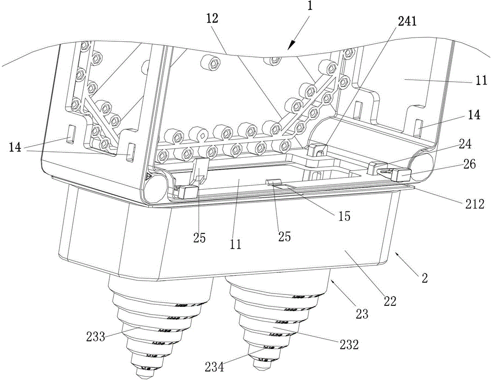
[0042] The mounting part is a buckle structure cooperating with the peripheral side wall of the wiring opening 11 of the distribution box 1 . The buckle structure is symmetrically arranged on the inner wall of the long side of the lower cover 21, and includes two pairs of inserts 24 symmetrical along the length direction arranged on both sides and a pair of facing toward the middle of the two inserts 24. Outer hook 25, such as image 3 and 4 As shown, the plug-in 24 is used to insert into the interior of the distribution box 1 from the peripheral side wall of the wiring opening 11 of the distribution box 1, and has an insertion hole 241 on its insertion end, and also includes a hook-shaped elastic latch 26 at the lower end. The latch 26 When inserted into the insertion hole 241 , its hook-shaped lower end is against the front edge of the insertion hole 241 , and the hook 25 is used to fasten with the peripheral side wall of the wiring opening 11 of the distribution box 1 . T...


PUM


Abstract

An electric cable incoming line sealing device includes a structural main body, a sealing piece sleeved on the electric cable incoming line in a hooping manner, and a mounting piece used for mounting the structural main body on a distribution box, wherein the structural main body includes a cubic lower cover and a cubic upper cover; the end part of the cover opening of the lower cover is matched with a wiring opening of the distribution box, and is connected with the distribution box through the mounting piece; the upper cover is sleeved at the outer part of the lower cover, and is fixed on the lower cover through hardware; at least one corresponding through hole is arranged in the cover top surface, opposite to the cover opening, of the upper cover, and at least one corresponding through hole is arranged in the cover top surface, opposite to the cover opening, of the lower cover, and the through holes are electric cable entrance holes; the sealing piece is a diaphragm seal made of flexible glue with enough toughness; and the diaphragm seal is clamped between the upper cover and the lower cover, and separates the electric cable entrance holes of the upper and the lower covers on the two sides of the diaphragm seal. The electric cable incoming line sealing device provided by the invention has a simple structure and is low in cost, holes are not needed to be field formed in the distribution box, and the sealing device adapts to various cables of different diameters for entrance.

Description

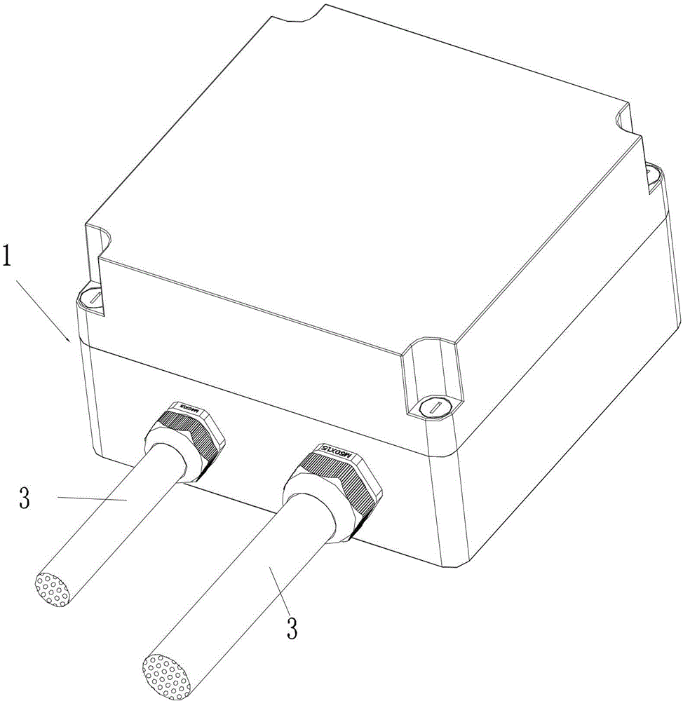
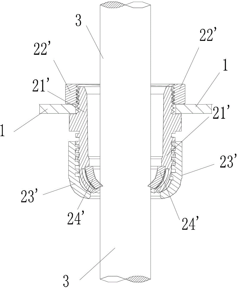
technical field [0001] The present invention relates to a sealing device used on an outdoor power distribution box for sealing when entering lines, in particular to a sealing device that adopts a soft rubber film to realize sealing, and also to a power distribution box with the sealing device . Background technique [0002] The distribution box is a power distribution device that assembles switchgear, measuring instruments, protective appliances and auxiliary equipment in the box according to the requirements of electrical wiring. The distribution box for outdoor work requires that the hole where the cable enters and exits on the side wall can be sealed to prevent the entry of rainwater and dust. The prior art usually uses cable entry glands to achieve this. like figure 1 , 2 As shown, the existing cable inlet gland is a cable inlet and outlet accessory similar to a bolt structure with a through hole, generally consisting of a gland main body 21', a gland fastening nut 22...

Claims


Application Information

Patent Timeline
Patent Type & Authority Patents(China)
IPC IPC(8): F16L5/02H02G3/18
Inventor 朱新平吴长松赵泓懿
Owner 朱新平
Learn More