Arrayed LED area light source
A LED surface light source, array-type technology, applied in the field of optical detection, can solve problems such as measurement errors and changes, and achieve the effects of improved detection accuracy, long service life, and good thermal stability
Inactive Publication Date: 2012-11-07
CHANGCHUN MATTEL INSTR
View PDF3 Cites 3 Cited by
- Summary
- Abstract
- Description
- Claims
- Application Information
AI Technical Summary
Problems solved by technology
From the above analysis, it can be concluded that in the case of non-perpendicular light irradiation, the change in the refractive index of the sample solution will cause the angle of the LED light entering the slit to change from the axis, resulting in a change in the intensity of the incident light, which will cause measurement errors
Method used
View moreImage
Smart ImageViewing Examples
Examples
Embodiment Construction
[0009] (5)
Login to View More PUM
 Abstract
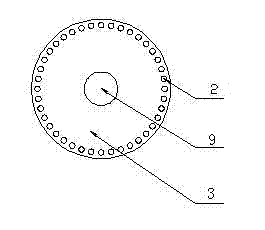
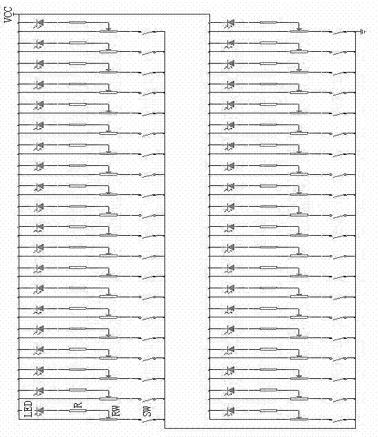
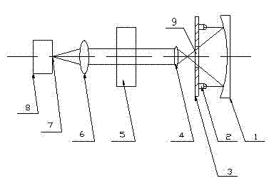
An arrayed LED area light source belongs to the field of optical detection and is capable of vertically illuminating sample solution. Arrayed LEDs are mounted on one surface of a circuit board, a circular hole is reserved at the center of the circuit board, a concave reflector is mounted on one surface, mounted with the LEDs, of the circuit board, a front convex lens is arranged on the other surface of the circuit board, a sample reservoir is arranged between the front convex lens and a rear convex lens, a light-splitting optical system is arranged behind the rear convex lens, and a slot is reserved on the light-splitting optical system. By above technical scheme, the arrayed LED area light source has the advantages that a plurality of LEDs are utilized as light sources to combine the arrayed LED area light source; is uniform in luminous intensity, good in heat stability and long in service life; and improves detection accuracy of the sample solution when being matched with a double focusing optical system. The arrayed LED area light source can be widely used to a detecting instrument of a light-splitting system.
Description
technical field [0001] The invention belongs to the field of optical detection. Background technique [0002] The technology of sample detection by spectrophotometry is quite mature and widely used. Among them, LED has been quite common as the instrument light source. And multiple LED arrays also appear in this type of testing instrument as the same instrument light source. However, people have also found some shortcomings of the LED array light source in long-term practice. When the LED array combined surface light source is used to directly illuminate the sample cell, the light emitted by each LED may not be irradiated vertically on the incident slit of the spectroscopic system, and most of the light sources enter at a certain angle to the vertical line of the incident slit. slit. [0003] Such as Figure 4 As shown, the solid line in the figure is the light emitted from the LED, passing through the sample solution and entering the incident slit. Let the ray deviate f...
Claims
Login to View More Application Information
Patent Timeline
 IPC IPC(8): F21S8/00F21V13/04G01N21/31F21Y101/02
Inventor 杨红冯旭东刘宏权
Owner CHANGCHUN MATTEL INSTR
Features
- R&D
- Intellectual Property
- Life Sciences
- Materials
- Tech Scout
- Unparalleled Data Quality
- Higher Quality Content
- 60% Fewer Hallucinations
Learn More Browse by: Latest US Patents, China's latest patents, Technical Efficacy Thesaurus, Application Domain, Technology Topic, Popular Technical Reports.
© 2025 PatSnap. All rights reserved.Legal|Privacy policy|Modern Slavery Act Transparency Statement|Sitemap|About US| Contact US: help@patsnap.com


