Valve assembly with adjustable spring preload and tool kit for adjusting the spring preload

A technology of valve device and regulating valve, applied in the direction of valve device, fluid pressure actuating device, function valve type, etc.

Inactive Publication Date: 2012-11-07
ROBERT BOSCH GMBH
View PDF9 Cites 0 Cited by
  • Summary
  • Abstract
  • Description
  • Claims
  • Application Information

AI Technical Summary

Problems solved by technology

[0004] The disadvantage of this solution is that a large number of structural elements must be provided for adjusting and supporting the adjusting spring and a large number of seals for sealing the spring chamber

Method used


Image

  • Valve assembly with adjustable spring preload and tool kit for adjusting the spring preload
  • Valve assembly with adjustable spring preload and tool kit for adjusting the spring preload
  • Valve assembly with adjustable spring preload and tool kit for adjusting the spring preload

Examples


Embodiment Construction

[0023] The basic construction of such a regulating valve arrangement 1 is described in detail in the prior art according to DE 101 36 416 A1 described at the outset. Furthermore, the schematic design of the pump regulator is explained in data sheet RD 92 711 / 10.07 issued by Bosch Rexroth AG, so only the structural elements which are relevant for understanding the invention are described below Also, for the sake of simplicity, reference is made to the aforementioned prior art.

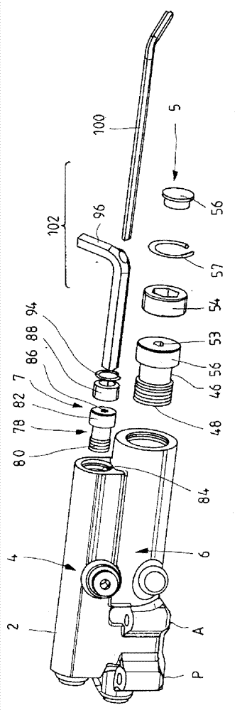
[0024] exist figure 1 The regulating valve arrangement 1 shown in has a valve housing 2 in which a delivery flow regulating valve 4 and a pressure regulating valve 6 are accommodated. The pressure regulating valve 6 keeps the pressure in the hydraulic system constant within the regulating range of the pump. With the aid of delivery flow regulating valve 4 , the delivery flow of the pump can be adjusted via the pressure difference across the load, so that the pump only delivers the amount of pressure m...


PUM


Abstract

The invention relates to a control valve assembly comprising a valve body which is prestressed in a direction by a control spring assembly. The spring preload of the control spring assembly (12, 62) can be adjusted by an adjusting device (5, 7) which is completely accommodated in the valve box (2) or a fitted housing part.

Description

technical field [0001] The invention relates to a valve arrangement according to the preamble of claim 1, in particular a control valve for a variable displacement pump, and to a set for adjusting the spring pretension of such a valve arrangement. Background technique [0002] A control valve assembly of the type described is known from DE 101 36 416 A1. The regulating valve subassembly has a valve housing, into which the pressure regulating valve and the delivery flow regulating valve are integrated. The regulating piston of the regulating valve is correspondingly pretensioned in one direction by means of the regulating spring. In known solutions, a spring housing is attached to the valve housing at the end face, in which spring housing a corresponding adjusting spring is arranged, which acts on the adjusting piston via a spring washer. superior. This adjusting spring itself is supported on a washer which can be adjusted in the axial direction by means of an adjusting sc...

Claims


Application Information

Patent Timeline
IPC IPC(8): F15B13/04F16K17/06
CPCF16K17/06F15B13/0402F16K13/00Y10T137/6065
Inventor C.施皮尔福格尔M.楚格
Owner ROBERT BOSCH GMBH
Why Eureka
Try Eureka