Fuel supply device for IC engine

A diesel engine and fuel technology, which is applied to fuel injection devices, charging systems, mechanical equipment, etc., can solve problems such as unreliable devices, poor fuel atomization, and wear, to prevent unwanted accumulation, ensure high reliability and safety effect

Inactive Publication Date: 2007-09-05
MAN DIESEL & TURBO FILIAL AF MAN DIESEL & TURBO SE TYSKLAND
View PDF5 Cites 0 Cited by
  • Summary
  • Abstract
  • Description
  • Claims
  • Application Information

AI Technical Summary

Problems solved by technology

At light loads this results in lower injection pressures and thus poor fuel atomization and incomplete combustion
The result is not only erratic operation, but also an undesired accumulation of residual oil which can lead to severe wear
Devices of known type have proven to be insufficiently reliable

Method used


Image

  • Fuel supply device for IC engine
  • Fuel supply device for IC engine
  • Fuel supply device for IC engine

Examples


Embodiment Construction

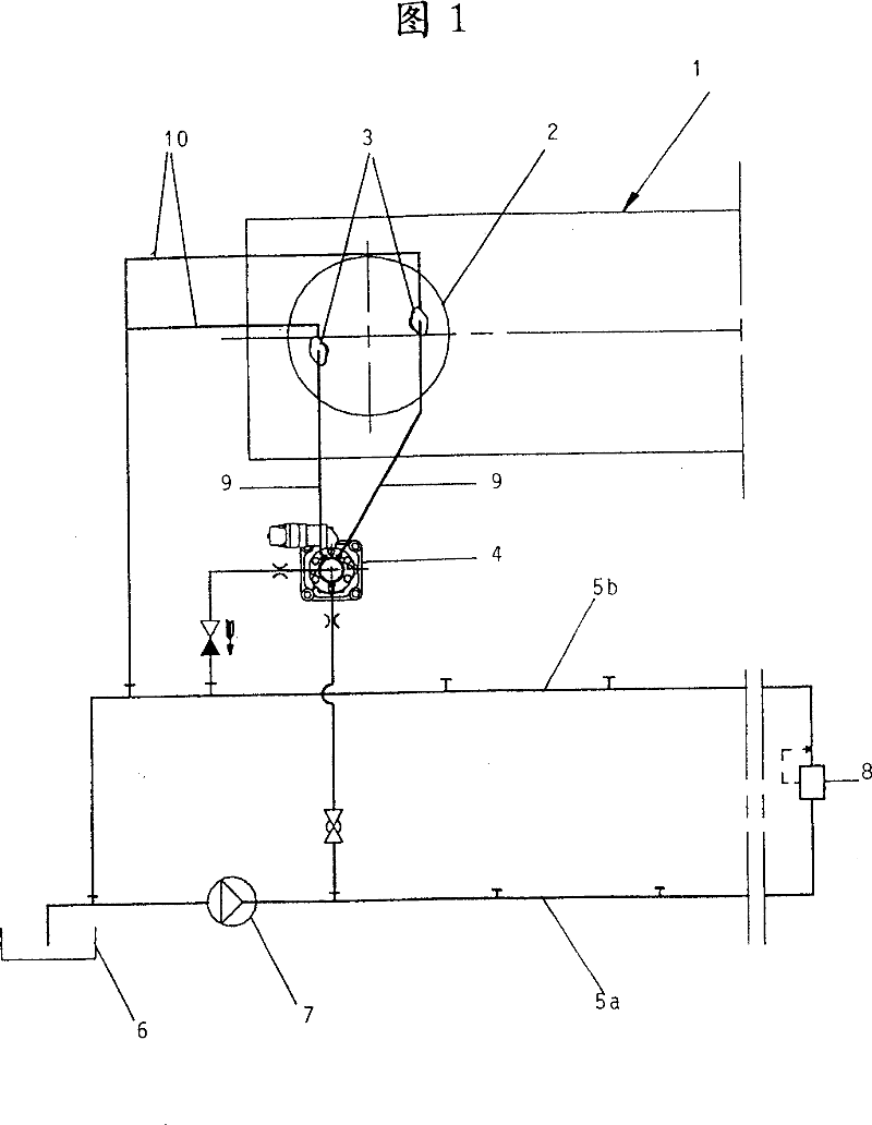
[0021] FIG. 1 schematically shows an internal combustion engine 1 , which may be a large two-stroke diesel engine, for example used as a marine power plant, comprising a plurality of cylinders 2 , only one of which is shown in FIG. 1 . Two fuel injectors 3 are provided per cylinder 2 , to which a common fuel injection pump 4 is always assigned. A common oil supply circuit is arranged for the fuel injection pumps 4 of all the cylinders 2. This oil supply circuit has a precursor branch line 5a and a return flow branch line 5b and is provided with a fuel tank 6, a preparation pump 7 and a pressure regulating valve 8. In the illustrated example, the oil supply circuit 5 is set at a pressure of 8 bar in the precursor branch line 5 a before the pressure regulating valve 8 , and the pressure in the return branch line 5 b after the pressure regulating valve 8 is 4 bar. The suction side of the fuel pump 4 is connected to the forward branch line 5a of the fuel supply circuit, and its re...


PUM


Abstract

The present invention relates to a device for supplying fuel of an internal combustion engine. Each injection valve disposed for each cylinder of the internal combustion engine has at least one flow channel 18 connecting to an injection hole forming part connectable to a pressure conduit capable of supplying fuel with a pressure source. The flow channel 18 penetrates through at least one closed body 35, and the closed body 35 can be energized to a seating part 38 due to the action of a force of a spring 45 and can be lifted from the corresponding seating part 38 by the fuel having a fuel pressure achieving to a certain set value. At this time, a force applied from a control piston 46 onto the closed body 35 is larger than a force applied onto the closed body 35 by fuel pressure in an usual opening pressure time and smaller than a force applied onto the closed body 35 by the highest limit fuel pressure, so that good behavior in partial load can be easily realized.

Description

technical field [0001] The present invention relates to a fuel supply device for an internal combustion engine, especially a large two-stroke diesel engine, which includes fuel injection valves configured for cylinders, preferably each cylinder has a plurality of fuel injection valves, wherein each of these fuel injection valves has at least one channel leading to The fuel injection hole can also be connected to a flow passage of a pressure pipe that can be supplied with fuel by means of a pressure source. The flow passage passes through at least one valve seat that can be pressed against the valve seat under the action of a spring and can be pumped by the fuel from the relevant pipe when the predetermined fuel pressure is reached. The closed body with the valve seat lifted. Background technique [0002] Such a device is known from EP0744007B1 of the applicant. In this known arrangement it is not possible to deactivate the injection valves individually. Consequently, all i...

Claims


Application Information

Patent Timeline
Patent Type & Authority Patents(China)
IPC IPC(8): F02M47/06F02M41/16F02B3/06F02B75/02F02D41/38F02M47/00F02M47/02F02M51/00F02M61/04F02M61/10F02M61/14F02M61/20F02M63/00
CPCF02M61/10F02M61/20F02B2075/025F02F2007/0097F02M63/0007F02M61/04F02M61/042F02B3/06F02M41/16
Inventor 拉尔斯·斯塔尔约翰尼斯·弗拉鲁普
Owner MAN DIESEL & TURBO FILIAL AF MAN DIESEL & TURBO SE TYSKLAND
Why Eureka
Try Eureka