Unlock instant, AI-driven research and patent intelligence for your innovation.

Lamp assembly

A technology for lamps and components, applied in electrical components, aircraft parts, electric lamp circuit layout, etc., can solve the problems of short operating life maintenance costs, endangering the safety of aircraft and passengers, and short operating life of incandescent filament lamps

Active Publication Date: 2012-11-07
SEOUL SEMICONDUCTOR
View PDF5 Cites 4 Cited by
  • Summary
  • Abstract
  • Description
  • Claims
  • Application Information

AI Technical Summary

Problems solved by technology

Incandescent filament luminaires are particularly prone to failure in aircraft environments due to large inrush currents and exposure to high levels of vibration, and the operational life of incandescent filament luminaires on aircraft compared lifespan may be relatively short
This relatively short operating life may at least involve considerable maintenance costs and, in the event of lamp failure during aircraft operation, may jeopardize the safety of the aircraft and passengers

Method used


Image

  • Lamp assembly
  • Lamp assembly
  • Lamp assembly

Examples


Embodiment Construction

[0018] Before describing the various embodiments in detail, it should be noted that the embodiments are not limited in application or use to the details of configuration and construction of parts shown in the drawings and description. The illustrated embodiments can be practiced or included in other embodiments, alterations and modifications, and can be practiced or carried out in various techniques. The light assembly configurations disclosed below are exemplary only and are not intended to limit the scope or application thereof. Furthermore, unless otherwise specified, the terms or expressions used herein are chosen for the purpose of describing the exemplary embodiments for the convenience of the reader and not for limiting the scope thereof.

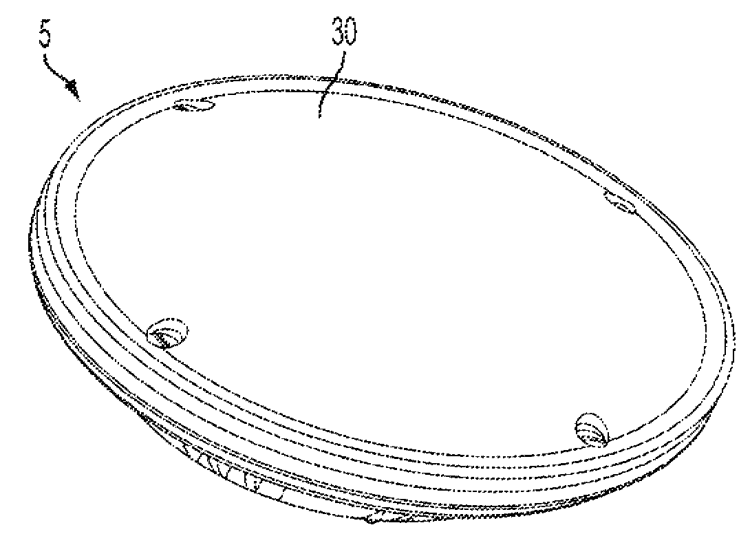
[0019] Figure 1A , 1B and 1C are front, rear and side perspective views, respectively, of a light fixture assembly 5 according to one embodiment. figure 2 is a perspective cross-sectional view of the lamp assembly 5, and image ...


PUM


Abstract

A lamp assembly including one or more light emitting diode (LED) arrays and a controller circuit to output a current to the one or more LED arrays. Each LED array includes at least one LED and defines a spatial radiation pattern having a first central axis. The lamp assembly also includes a lens array to redirect light received from the one or more LED arrays, a base and a light-transmissive cover. For each one of the one or more LED arrays, the lens array includes a total internal reflection (TIR) lens defining a second central axis aligned with the first central axis of the corresponding LED array. The TIR lens is configured to distribute light received from the LED array from an output face of the TIR lens such that the distributed light defines optical paths that are convergent, divergent or collimated with respect to the second central axis. The base includes a first surface to receive the one or more LED arrays, the controller circuit and the lens array. The base also includes a second surface structured to be removably received by a lamp holder. The light-transmissive cover is attached to the base and disposed over the first surface thereof such that the one or more LED arrays, the controller circuit and the lens array are contained between the cover and the base.

Description

Background technique [0001] Virtually all types of commercial and private aircraft include exterior lights, such as taxi and landing lights, to ensure proper visibility of the aircraft in a wide range of natural lighting conditions. Requirements determining the number and configuration of such lights are, among other things, usually embodied in regulations relating to airworthiness standards, such as Title 14, Part 23 of the Code of Federal Regulations. Exterior aircraft lights typically utilize incandescent filament technology. Incandescent filament luminaires are particularly prone to failure in aircraft environments due to large inrush currents and exposure to high levels of vibration, and the operational life of incandescent filament luminaires on aircraft compared Lifespan may be relatively short. This relatively short operating life may at least involve considerable maintenance costs and, in the event of a lamp failure during aircraft operation, may jeopardize the safe...

Claims


Application Information

Patent Timeline
IPC IPC(8): H05B41/36H05B37/02
CPCF21V31/005F21V17/005F21V29/2293F21Y2105/001B64D2203/00B64D47/06F21V19/0055B64D47/04H05B33/089F21V5/007F21V19/0035F21V17/12F21V23/005F21V7/0091F21Y2101/02F21V29/83F21Y2105/10F21Y2115/10F21W2107/10F21W2107/17F21W2107/30H05B45/50H05B45/38H05B45/56Y02B20/30
Inventor G.W.帕纳戈塔科斯D.G.佩尔卡
Owner SEOUL SEMICONDUCTOR