Hydraulic pushing driving device in piston pushing centrifuge

A driving device, hydraulic technology, applied in the direction of centrifuges, etc., can solve problems such as troublesome installation, material pollution, oil circuit pressure reduction, etc., and achieve the effect of simple installation, stable working process and avoiding pollution

Active Publication Date: 2012-11-14
JIANGSU HUADA CENTRIFUGE
View PDF7 Cites 6 Cited by
  • Summary
  • Abstract
  • Description
  • Claims
  • Application Information

AI Technical Summary

Problems solved by technology

Commonly used hydraulic pusher drive devices, the hydraulic oil distribution and reversing mechanism and other components and oil cylinders are independent of each other, and the oil passages between them are connected by oil pipes and pipe joints. The structur

Method used


Image

  • Hydraulic pushing driving device in piston pushing centrifuge
  • Hydraulic pushing driving device in piston pushing centrifuge
  • Hydraulic pushing driving device in piston pushing centrifuge

Examples


Embodiment Construction

[0013] The specific embodiments of the present invention will be described in detail below in conjunction with the accompanying drawings.

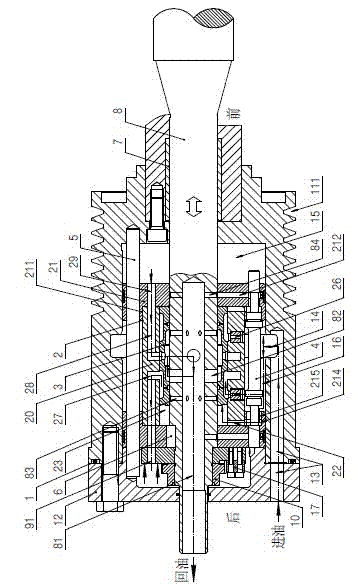
[0014] Such as figure 1 As shown, a hydraulic pushing drive device in a piston pushing centrifuge, its structure includes a cylinder 1 made of a cylinder 11 and a cylinder head 12 arranged on the cylinder 11 through a sealing ring, and a cylinder 1 that moves through the The bottom wall of the cylinder barrel 11 and the push rod 8 of the cylinder head 12, the outer peripheral surface of the cylinder barrel 11 is provided with a timing belt groove 111, and an axial oil inlet passage 13 is opened in the cylinder barrel 11 and the cylinder head 12. The oil inlet passage 13 is formed by each section of the oil inlet passage of the cylinder barrel 11 and the cylinder head 12, and there is also a reliable sealing connection between each section of the oil inlet passage of the cylinder barrel 11 and the cylinder head 12. The sealing ring of the ...


PUM


Abstract

The invention discloses a hydraulic pushing driving device in a piston pushing centrifuge which is simple in installment and can improve the reliability. The hydraulic pushing driving device comprises a cylinder body and a pushing rod arranged inside the cylinder body in a penetrated mode; a piston is sleeved on the pushing rod in the inner cavity of the cylinder body; an oil line reversing drum is arranged between the piston and the pushing rod; the piston consists of a piston body and piston seats placed at the two ends of the piston body; mutually matched oil lines are arranged among the piston, the oil line reversing valve, the cylinder body and the pushing rod; and a reversing driving rod for switching the reversing oil lines of the oil line reversing drum is arranged between piston seats in a penetrated mode. According to the hydraulic pushing driving device in the piston pushing centrifuge, the hydraulic pressure distribution and the reversing components are skillfully integrated in the piston cylinder body, so that a reversing motion and a pushing reciprocating motion are simultaneously finished; with the adoption of the integrated structure, the installment of the whole pushing driving device becomes very simple, and the non-blind area reversion of the oil line reversing drum is achieved, so that the working process is very stable and reliable; and the pollution of the material in the rotary drum because of oil leakage can be avoided.

Description

technical field [0001] The invention relates to a piston pusher centrifuge, in particular to a hydraulic pusher drive device in the piston pusher centrifuge. Background technique [0002] The pusher drive device in the piston pusher centrifuge is usually divided into two types: mechanical or hydraulic. The pusher drive device rotates at the same speed and in the same direction as the drum, and pushes the material back and forth with the pusher plate. At present, the hydraulic pusher driving device is also divided into various forms, which are mainly reflected in the differences in the structure of the oil cylinder and piston, the way of oil intake, and the hydraulic control system. Commonly used hydraulic pusher drive devices, the hydraulic oil distribution and reversing mechanism and other components and oil cylinders are independent of each other, and the oil passages between them are connected by oil pipes and pipe joints. The structure is messy and it is troublesome to i...

Claims


Application Information

Patent Timeline
IPC IPC(8): B04B9/06
Inventor 吴志明史学礼蔡建春
Owner JIANGSU HUADA CENTRIFUGE
Why Eureka
Try Eureka