Relief printing plate structure

A technology for printing letterpress and graphics, applied to printing plates, printing, printing machines, etc., can solve problems such as abnormal orientation of liquid crystal molecules, uneven surrounding colors, affecting product quality and yield, etc., to improve width and thickness, and reduce vibration And boundary pressure, guarantee the effect of printing and display effect

Inactive Publication Date: 2014-12-24
BOE TECH GRP CO LTD +1
View PDF13 Cites 0 Cited by
  • Summary
  • Abstract
  • Description
  • Claims
  • Application Information

AI Technical Summary

Problems solved by technology

[0009] The purpose of the present invention is to provide a printing relief structure, to overcome the existing printing relief structure is easy to cause the abnormal alignment film around the liquid crystal display screen, resulting in abnormal orientation of liquid crystal molecules, uneven color or mura around the phenomenon that affects product quality and good quality. Defects such as rate

Method used


Image

  • Relief printing plate structure
  • Relief printing plate structure
  • Relief printing plate structure

Examples


Embodiment Construction

[0026] The specific implementation manners of the present invention will be further described in detail below in conjunction with the accompanying drawings and embodiments. The following examples are used to illustrate the present invention, but are not intended to limit the scope of the present invention.

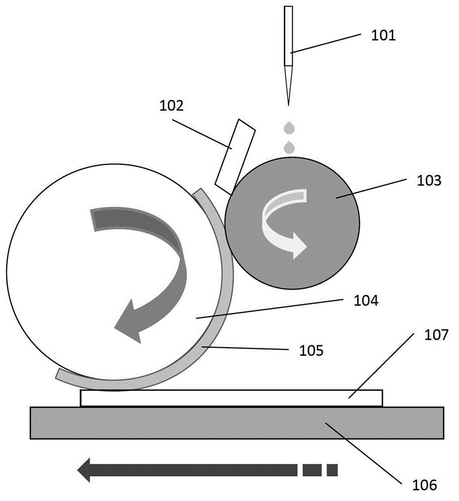
[0027] refer to figure 1 , is a schematic diagram of the principle of the PI film letterpress printing process. The process specifically includes: the dispenser Dispenser 101 spits out the PI liquid and drops it onto the surface of the Anilox roller 103 , while the scraper Blade 102 smoothes the PI liquid on the Anilox roller 103 . The Anilox roller 103 keeps rotating counterclockwise. At the same time, the printing roller Print Roll 104 rotates clockwise, and the printing roller 104 drives the printing relief 105 mounted on it to rotate clockwise. Through the contact and extrusion of the printing relief 105 and the Anilox roller 103 The PI liquid is transferred to each ...


PUM


Abstract

A relief printing plate comprises a bearing base plate (301) and a plurality of printing patterns arranged on the bearing base plate. A space area is arranged between adjacent printing patterns. The printing pattern comprises a middle area (302) corresponding to a display area and a boundary area (304) corresponding to a non-display area, the boundary area being arranged on two sides of the middle area, and an inclined slope (404) being arranged on the boundary area along the printing direction. The relief printing plate can effectively reduce shock and boundary pressure during printing, and print an orientation material on a glass base plate evenly, so as to improve the width and the thickness of an HALO area, prevent the HALO area from affecting the liquid crystal display area, and effectively guarantee printing and display effects of an orientation film.

Description

technical field [0001] The invention relates to the field of display technology, in particular to a printing relief structure. Background technique [0002] In the manufacturing process of liquid crystal display devices (LCD), it is necessary to coat the upper and lower substrates of the display device with PI (Polyimide, polyimide) alignment film, and letterpress is more mature and widely used in the liquid crystal display manufacturing industry. Printing Technology. [0003] Such as figure 1 As shown, the basic process of letterpress printing is described as follows: First, the dispenser (Dispenser) 101 drops PI liquid onto the anilox roll 103 (Anilox Roll), and at the same time, the doctor blade (Blade) 102 wipes the PI liquid on the Anilox roll 103 Then, the PI liquid is transferred to the relief plate (APR) 105 mounted on the printing roll (Print Roll) 104 by the rotation of the Anilox roll 103 . Finally, the PI liquid is transferred to the surface of the substrate 1...

Claims


Application Information

Patent Timeline
Patent Type & Authority Patents(China)
IPC IPC(8): B41F5/00
CPCB41N1/12G02F1/13378G02F1/1303
Inventor 刘锋邓金阳杭苗
Owner BOE TECH GRP CO LTD
Why Eureka
Try Eureka