
Welding bar box

A welding rod box and the other side technology, applied in packaging and other directions, can solve the problems of poor welding rod dispersion effect and complex structure, and achieve the effects of simple structure, solving welding rod accumulation and low processing cost.

Inactive Publication Date: 2012-11-14
TIANJIN MINGTANG ENVIRONMENTAL PROTECTION TECH
View PDF0 Cites 0 Cited by
  • Summary
  • Abstract
  • Description
  • Claims
  • Application Information

AI Technical Summary

Problems solved by technology

[0002] In the existing welding rod packaging production line, the welding rod box with no gap at the bottom is generally used. In the process of vibrating and dispersing the welding rod, in order to make the vibration dispersing equipment achieve the purpose of dispersing the welding rod, it is necessary to join the symmetrical transmission at both ends of the bottom of the welding rod box. Vibration plate, this kind of welding rod box not only has the problem of complex structure, but also has no obvious effect on the dispersion of welding rods

Method used


Image

  • Welding bar box
  • Welding bar box
  • Welding bar box

Examples


Embodiment Construction

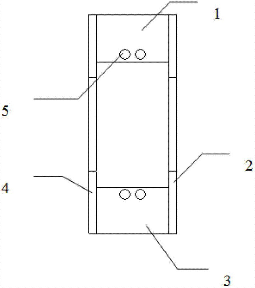
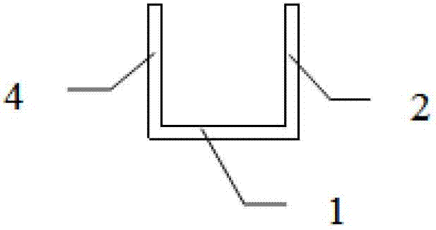
[0017] like figure 1 , 2 , 3, the present invention provides a welding rod box, the welding rod box is composed of a first bottom block 1, a second bottom block 3, a first side 2 and a second side 4, the first bottom block 1 Arranged in parallel with the second bottom block 3 at the same height and at intervals, the first side 2 is located on one side of the first bottom block 1 and the second bottom block 3 and is perpendicular to the first bottom block 1 and the second bottom block The plane where the block 3 is located, the second side 4 is located on the other side of the first bottom block 1 and the second bottom block 3 and is perpendicular to the plane where the first bottom block 1 and the second bottom block 3 are located, the first bottom block 1. The second bottom block 3 , the first side 2 and the second side 4 enclose the bottom through hole of the welding rod box, and there is a lower gap under the first side 2 and the second side 4 respectively.

[0018] The f...


PUM


Abstract

The invention provides a welding bar box, consisting of a first bottom block, a second bottom block, a first lateral edge and a second lateral edge. The first bottom block and the second bottom block are arranged at an interval and in parallel at the same height; the first lateral edge is located at one sides of the first bottom block and the second bottom block and is vertical to a plane wherein the first bottom block and the second bottom block are arranged; the second lateral edge is located at the other sides of the first bottom block and the second bottom block and is vertical to the plane where the first bottom block and the second bottom block are arranged; a bottom through hole of the welding bar box is defined by the first bottom block, the second bottom block, the first lateral edge and the second lateral edge; and a lower notch is arranged below each of the first lateral edge and the second lateral edge. The welding bar box provided by the invention has the following beneficial effects: in a welding bar package production line, the welding bar box is arranged above vibration diffusion equipment, so that the vibration diffusion equipment can pass through the through hole at the bottom of the welding bar box to contact welding bars in the welding bar box when the equipment vibrates up and down. Therefore, the purpose of diffusing the welding bars in time is reached, and the problem of the accumulation of the welding bars can be solved.

Description

technical field [0001] The invention belongs to the field of welding rod boxes, and in particular relates to a welding rod box used in conjunction with welding rod vibration dispersion equipment in a welding rod packaging production line. Background technique [0002] In the existing welding rod packaging production line, the welding rod box with no gap at the bottom is generally used. In the process of vibrating and dispersing the welding rod, in order to make the vibration dispersing equipment achieve the purpose of dispersing the welding rod, it is necessary to join the symmetrical transmission at both ends of the bottom of the welding rod box. Vibrating plate, this kind of welding rod box not only has the problem of complex structure, but also has no obvious effect on the dispersion of welding rods. Contents of the invention [0003] The problem to be solved by the present invention is to provide a welding rod box, which is especially suitable for use in conjunction wi...

Claims


Application Information

Patent Timeline
Patent Type & Authority Applications(China)
IPC IPC(8): B65B35/06
Inventor 刘建柏涛李力么德英周士杰赵春福
Owner TIANJIN MINGTANG ENVIRONMENTAL PROTECTION TECH
Learn More