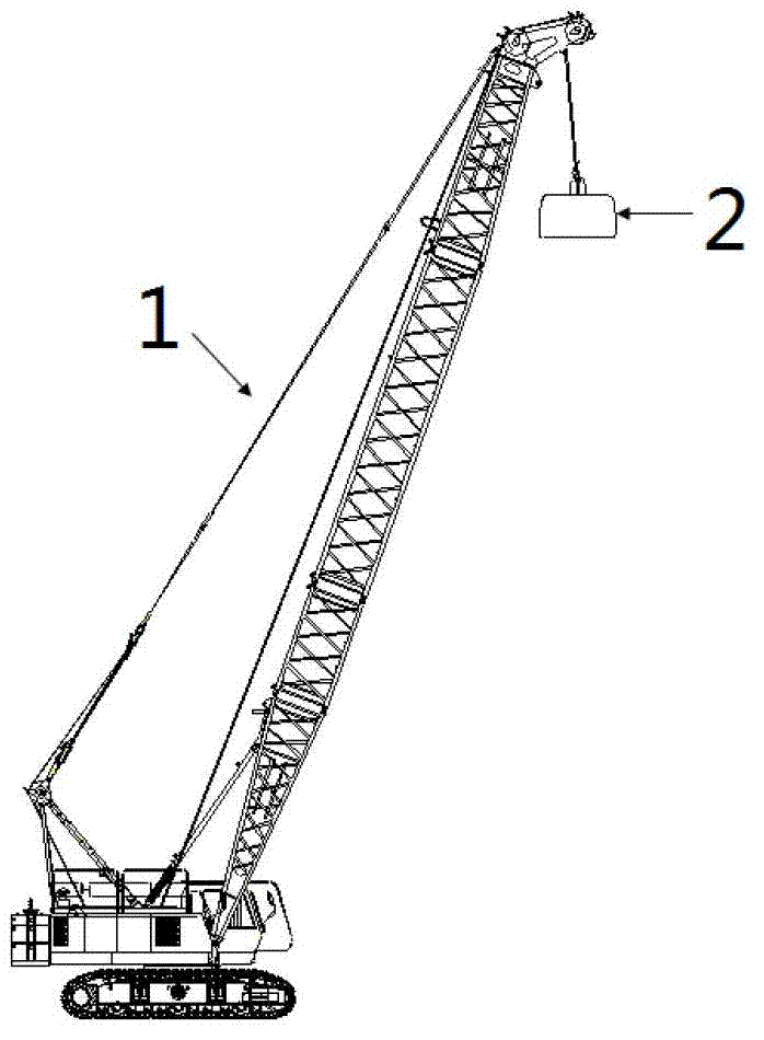
Ramming hammer

A rammer-integrated technology, applied in soil protection, construction, infrastructure engineering, etc., can solve the problems of high cost, broken rammer, different impact force, etc. low height effect

Active Publication Date: 2012-11-14
XCMG CONSTR MACHINERY
View PDF7 Cites 0 Cited by
  • Summary
  • Abstract
  • Description
  • Claims
  • Application Information

AI Technical Summary

Problems solved by technology

[0003] At present, the commonly used rammers in China include: cast steel rammers, cast iron rammers, and combined rammers made of plates. However, among them, the combined rammers made of plates are the most costly, and cast steel rammers use The material is cast carbon steel (cast carbon steel is cast steel with carbon as the main alloying element and contains a small amount of other elements), the material used for cast iron rammer is cast iron (cast iron is an alloy mainly composed of iron, carbon and silicon), and the cost are high
[0004] In addition, due to the uneven distribution of hard objects such as crushed stones, flakes and slag on the foundation, the impact force on the bottom of the rammer when it touches the foundation is also different, and the rammer is the part with the highest working frequency on the dynamic compaction machine, so In the process of compacting the foundation, it is easy to cause the rammer to break

Method used


Image

  • Ramming hammer
  • Ramming hammer
  • Ramming hammer

Examples


Embodiment Construction

[0026] The technical solutions of the present invention will be described in further detail below with reference to the accompanying drawings and embodiments.

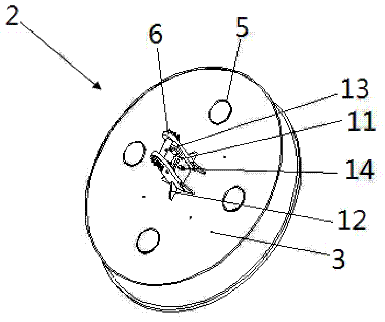
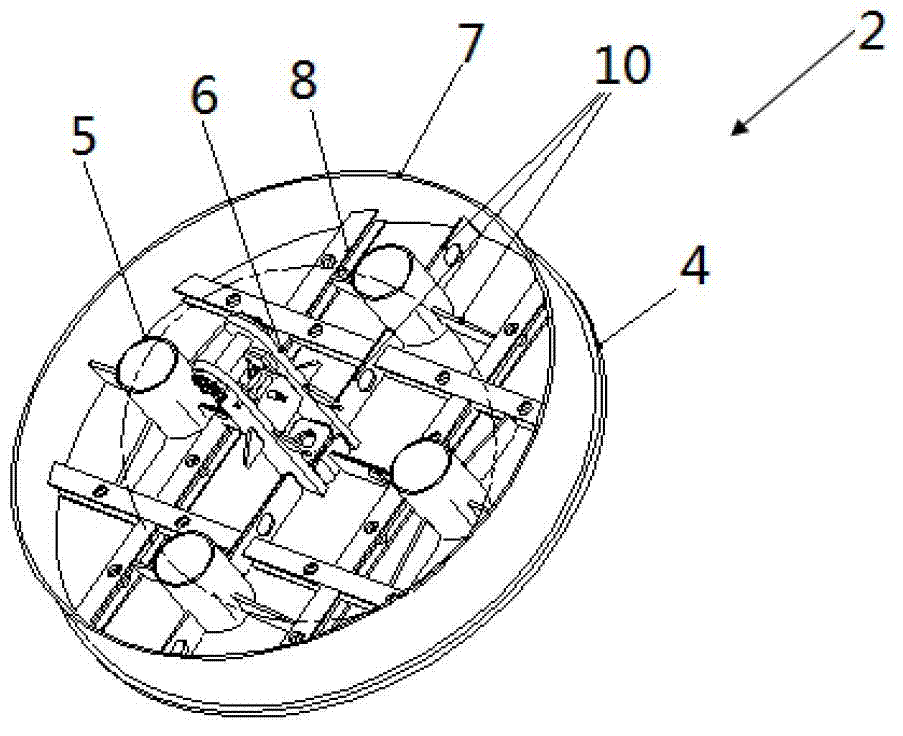
[0027] figure 2 with image 3 One embodiment of the rammer provided by the present invention is shown, as figure 2 , image 3 As shown, the rammer includes a base and a cover plate 3, the base and the cover plate 3 form a closed space, a steel frame and a lifting rib 6 welded on the bottom plate 4 of the base, and cast in the gap of the closed space of concrete (concrete not shown in the diagram). Wherein, the lifting ribs 6 all run through the cover plate 3, and the lifting ribs 6 and the cover plate 3 are welded into one body, and the lifting ribs 6 are provided with lifting parts.

[0028] In this embodiment, the base can include a bottom plate 4 and a side wall 7, and the bottom plate 4 and the side wall 7 are welded together. At this time, the closed space is a hollow cylindrical cavity. Obviously, the close...


PUM


Abstract

The invention relates to a ramming hammer which comprises a base and a covering plate, wherein a sealed space is formed between the base and the covering plate; the ramming hammer further comprises a steel frame and a crane rib welded on a base plate of the base, and concrete poured into the gap of the sealed space; wherein the crane rib runs through the covering plate and is welded with the covering plate integrally; and the crane rib is provided with a crane piece. The ramming hammer provided by the invention is not only low in cost, but also resistant in throwing, and is applicable for a dynamic compactor with low ramming power.

Description

technical field [0001] The invention relates to a dynamic compactor, in particular to a rammer in the dynamic compactor. Background technique [0002] Such as figure 1 As shown, the dynamic compaction method is also called the dynamic consolidation method, that is, the lifting equipment (such as figure 1 The dynamic tamping machine shown in 1) repeatedly raises the rammer 2 to a certain height, and the rammer 2 falls freely after uncoupling under the action of the uncoupling device, and the potential energy is converted into kinetic energy. When the rammer 2 touches the foundation, its kinetic energy will form a strong shock wave and high stress on the foundation, which can increase the strength of the foundation, reduce the compressibility of the foundation, improve the resistance to vibration (shock) vibration and liquefaction of the foundation, and eliminate Collapsibility, etc. [0003] At present, the commonly used rammers in China include: cast steel rammers, cast i...

Claims


Application Information

Patent Timeline
Patent Type & Authority Applications(China)
IPC IPC(8): E02D3/046
Inventor 周波柯春林赵波章琢
Owner XCMG CONSTR MACHINERY
Why Eureka
Try Eureka