

Method and device for compensating field sequential backlight color
A compensation method and field sequential technology, applied in the field of backlight, can solve problems such as poor color expression and poor color saturation
- Summary
- Abstract
- Description
- Claims
- Application Information
AI Technical Summary
Problems solved by technology
Method used
Image

Examples
Embodiment Construction
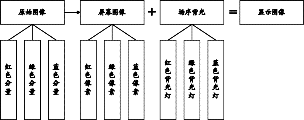
[0034] The basic idea of the present invention is: by compensating the brightness of a single light-emitting diode (including red light, green light, and blue light) of the backlight source and the screen image displayed on the liquid crystal screen, the color saturation of the field sequential backlight technology can be improved. In order to solve the problem of poor color expression and poor color saturation of field sequential technology.
[0035] In order to make the object, technical solution and advantages of the present invention clearer, the present invention will be further described in detail by citing the following embodiments and referring to the accompanying drawings.
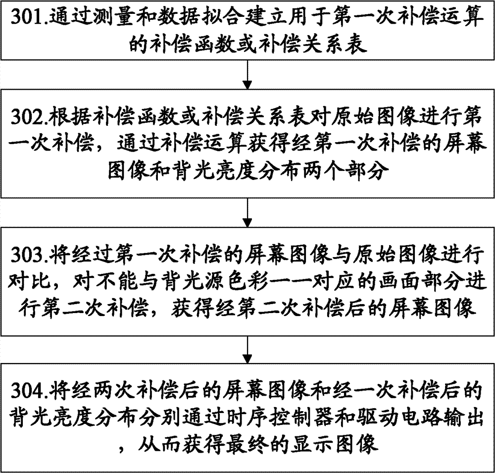
[0036] image 3 The implementation flowchart of the field sequential backlight color compensation method provided by the present invention, the method uses two compensation methods to improve the color saturation of the field sequential backlight technology, and the specific steps are as follows...
PUM
 Abstract
Description
Claims
Application Information