High quality spinning dyeing mechanism

A high-quality, textile technology, applied in the field of textile printing and dyeing, can solve problems such as uneven dyeing and easy fading, and achieve uniform dyeing, improved fastness, and stable performance

Inactive Publication Date: 2017-08-11
CHANGXING COUNTY DAWEI TEXTILE CO LTD
View PDF1 Cites 12 Cited by
  • Summary
  • Abstract
  • Description
  • Claims
  • Application Information

AI Technical Summary

Problems solved by technology

[0005] The purpose of the present invention is to provide a high-quality textile dyeing mechanism for the deficiencies of the prior art. Cloth wrink

Method used


Image

  • High quality spinning dyeing mechanism
  • High quality spinning dyeing mechanism
  • High quality spinning dyeing mechanism

Examples


Embodiment 1

[0037] The embodiments are described below with reference to the accompanying drawings. The embodiments shown below do not limit the invention content described in the claims. required for the solution.

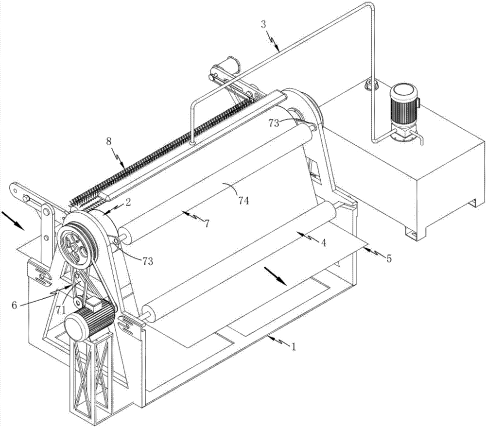
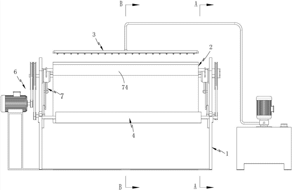
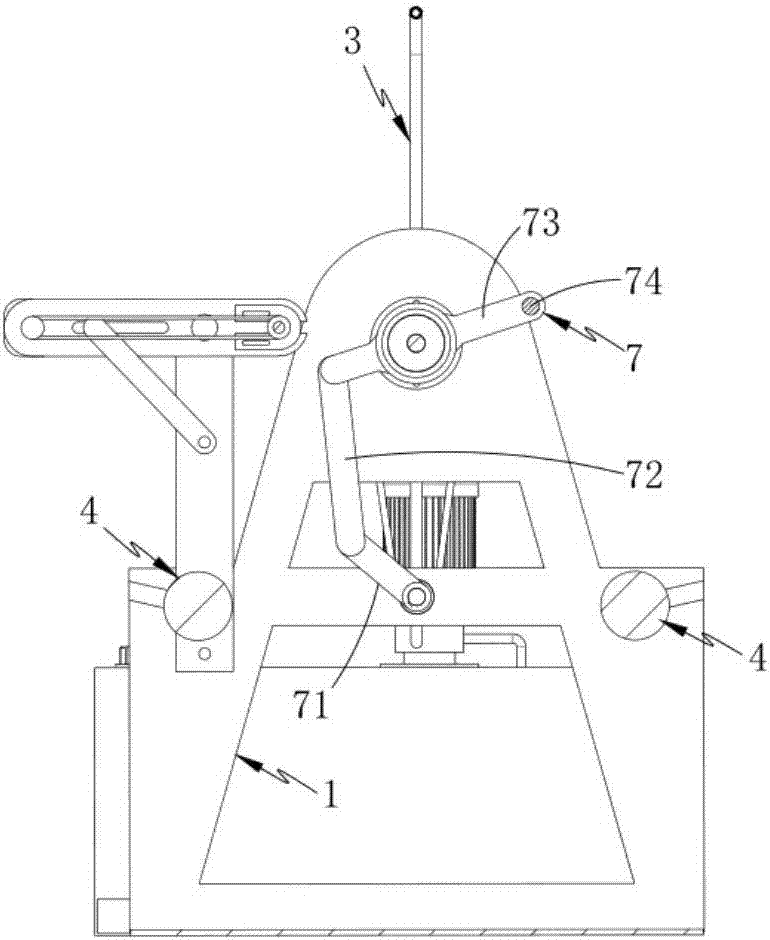
[0038] Such as figure 1 , 2 , 3, a high-quality textile dyeing mechanism, including a frame 1, a transmission roller 2 rotatably mounted on the frame 1, a dyeing assembly 3 fixedly arranged above the transmission roller 2, and a rotatably mounted frame 2 1 and the cloth guide roller 4 located on both sides of the transfer roller 2 and the driving assembly 6 that drives the transfer roller 2 to carry out the transfer of the gray cloth 5; The upper surface is in contact; it also includes a smear assembly 7 located on one side of the transmission roller 2 and moving along its outer circumferential surface. The greige cloth carries out the even application of dye liquor, and this application assembly 7 comprises:

[0039] A first connecting rod 71, one end of the first connec...

Embodiment 2

[0053] Components that are the same as or corresponding to those in the first embodiment use the reference numerals corresponding to those in the first embodiment. For the sake of simplicity, only the differences from the first embodiment are described below. The difference between this embodiment two and embodiment one is: as Figure 6 As shown, in this embodiment, the spraying dyeing assembly 3 is arranged directly above the conveying roller 2, and the axes of the two are located in the same vertical plane. During the spraying process, the dyeing liquid is sprayed on the gray cloth 5 , form pre-dyeing area 31, dyeing area 32 and touch-up area 33 successively along its conveying direction, wherein dyeing area 32 is positioned at the area that forms directly below the spraying mouth of spray-dye assembly 3, and pre-dyeing area 31 and touch-up area 33 with The dyeing areas 32 are arranged symmetrically.

[0054] Further, 1 and 4 also include a cleaning mechanism 8 located in t...

Embodiment 3

[0058] Components that are the same as or corresponding to those in Embodiment 2 use reference numerals corresponding to those in Embodiment 1. For the sake of simplicity, only the differences from Embodiment 2 will be described below. The difference between the third embodiment and the second embodiment is: as Figure 7 As shown, the spray dyeing assembly 3 is arranged above the transmission roller 2 and is biased toward the applicator roller 74. During the spray dyeing process, the dye solution is sprayed on the gray cloth 5, and the dyeing area 32' and touch-up are followed along the conveying direction. Area 33', wherein the dyeing area 32' is located in the area formed directly below the dyeing port of the spraying assembly 3, the spraying liquid volume of the spraying assembly 3 is constant, and the area of ​​the embryo cloth 5 sprayed and dyed is reduced, thereby improving the quality of the embryonic cloth. Cloth 5 dyeing efficiency.


PUM


Abstract

The invention relates to a high-quality textile dyeing mechanism, which includes a frame, a transmission roller rotatably mounted on the frame, a spraying and dyeing assembly fixedly arranged above the transmission roller, and a rotatively mounted frame located on both sides of the transmission roller The cloth guide roller and the driving assembly that drives the transmission roller to carry out gray cloth transmission also include a smear assembly that is located on one side of the transmission roller and moves along its outer circumference. The first connecting rod connected to the driving assembly, the second connecting rod connected to the other end of the first connecting rod in rotation, the third connecting rod connected to the second connecting rod at one end and installed on the second connecting rod The smearing roller at the other end of the three connecting rods; the greige cloth is pre-dyed, dyed and polished, and then reciprocated on the conveying roller by the smearing roller to achieve wrinkle removal, color fixation and uniform dyeing of the greige cloth. The technical problems of uneven dyeing and easy fading in the background technology.

Description

technical field [0001] The invention relates to the field of textile printing and dyeing, in particular to a high-quality textile dyeing mechanism. Background technique [0002] The textile industry is an important industry of our country's national economy. For a long time, the textile industry has made significant contributions to the development of the national economy, solving the problem of people's clothing, and earning foreign exchange through exports. The dyeing and finishing industry as a connecting bridge undoubtedly plays an important role in this industry. status. The dyeing and finishing industry is the key to deep processing, finishing and added value of textiles. It is the link between textile fibers, raw yarns, and gray cloths processed into final products entering the consumer market, and plays an important role in promoting the common development of products; The industry is mainly based on dip dyeing and spray dyeing. Compared with spray dyeing, printing ...

Claims


Application Information

Patent Timeline
IPC IPC(8): D06B1/14D06B1/02D06B23/04
CPCD06B1/145D06B1/02D06B23/04
Inventor 臧伟
Owner CHANGXING COUNTY DAWEI TEXTILE CO LTD
Why Eureka
Try Eureka