Imaging Device

a technology of imaging device and image, which is applied in the direction of picture signal generator, solid-state device signal generator, television system, etc., can solve the problems of image obtained by the near infrared camera that is not monochromatic, and has a general linear photoelectric conversion characteristic that cannot accurately acquire luminance distribution on a dark or bright side, etc., to achieve enhanced s/n ratio, wide dynamic range, and prevent the effect of color signal saturation reduction

Inactive Publication Date: 2013-08-15
KONICA MINOLTA OPTO
View PDF10 Cites 15 Cited by
  • Summary
  • Abstract
  • Description
  • Claims
  • Application Information

AI Technical Summary

Benefits of technology

[0016]The invention is directed to an imaging device provided with an imaging optical system, an imaging element, and an image processing section. The imaging device is configured in such a manner that original image data including at least three types of original image components is obtained by using the imaging element which has a sensitive wavelength region including an infrared wavelength region, and selectively including a visible wavelength region, and which is composed of at least three types of pixels having spectral sensitivities different from each other. The imaging device is configured to compress the dynamic range of the original image data including the three types of original image components, and to generate a color image based on a luminance signal including an infrared wavelength component that has been generated based on the compressed original image data, and based on a color-difference signal that has been generated based on the visible wavelength component in the original image data. With this configuration, it is possible to prevent lowering of saturation of a color signal resulting from compression of the dynamic range including an infrared wavelength component, and to obtain a clear color image having an enhanced S / N ratio at nighttime, and having a wide dynamic range.

Problems solved by technology

An imaging element having a general linear photoelectric conversion characteristic cannot accurately acquire a luminance distribution on a dark portion or a bright portion even with respect to an ordinary subject due to the narrow dynamic range thereof.
Further, although an imaging element with a logarithmic conversion type photoelectric conversion characteristic has a sufficiently wide dynamic range with respect to an ordinary subject, the imaging element may have a poor sensitivity on the low luminance side.
However, an image obtained by the near infrared camera is monochromatic and is different from an image directly viewed by human eyes.
This may provide the viewers incongruity.
However, since the quantity of photon is small at nighttime, the S / N ratio of an image obtained at nighttime may be small.
Further, non-patent literature 1 involves a drawback that an image may be less visible, because the viewer may be blinded by strong light such as headlight from an opposing automobile.

Method used


Image

  • Imaging Device
  • Imaging Device
  • Imaging Device

Examples


first embodiment

[0134]The first embodiment as described above may also be applied to an imaging element having a configuration different from the configuration shown in FIG. 2. In the following, a second example of the configuration of the imaging element is described referring to FIG. 10 and FIG. 11. FIG. 10 is a schematic diagram showing the second example of the configuration of the imaging element.

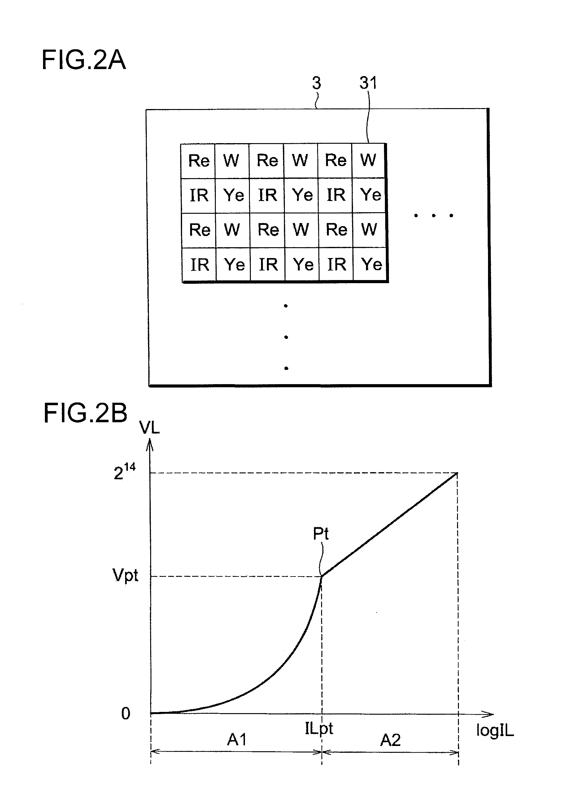
[0135]Referring to FIG. 10, an imaging element 3 is a linear-log sensor substantially the same as the one shown in FIG. 2. The imaging element 3 has a number of pixels 31 arranged in a two-dimensional matrix. The imaging element 3 is configured in such a manner that pixels 31, in each of which one of four types of filters i.e. a blue (B) filter, a green (G) filter, a red (R) filter, and an infrared transmissive (IR) filter is provided, are regularly arranged.

[0136]In the example shown in FIG. 10, pixels 31 provided with B filters, and pixels 31 provided with R filters are alternately arranged in a cer...

second embodiment

[0161]FIG. 16 is a block diagram showing a configuration of an image processing section 4 in the

[0162]Referring to FIG. 16, the image processing section 4 has a D-range expander 49 at a position anterior to a pixel corrector 41 corresponding to the pixel corrector 41 in the first embodiment shown in FIG. 4.

[0163]The D-range expander 49 combines and generates D-range expanded original image data D3 (Ye, M, C, W) by the method described referring to FIG. 14A, based on image data D31 (Ye, M, C, W) which is obtained by an imaging operation of the imaging element 3 for the first exposure time T1, and based on image data D32 (Ye, M, C, W) which is obtained by an imaging operation of the imaging element 3 for the second exposure time T2 different from the first exposure time T1, succeeding the image data D31. Thereafter, image processing is performed with use of original image data D3. Since the configuration of the pixel corrector 41 thereafter is substantially the same as the configurati...

third embodiment

[0173]As described above, in the imaging device of the third embodiment provided with an imaging optical system, an imaging element having a knee characteristic, and an image processing section, original image data is obtained by using the imaging element which has a sensitive wavelength region including an infrared wavelength region, and selectively including a visible wavelength region, and which is composed of four types of pixels having spectral sensitivities different from each other. The imaging device is configured to extract a luminance signal including an infrared wavelength component, and a color-difference signal from the original image data; and to modulate the color-difference signal based on a high frequency component in the luminance signal including the infrared wavelength component. With this configuration, it is possible to provide the imaging device that enables to prevent fake color generation in an edge portion, resulting from the color filter arrangement of the...


PUM


Abstract

An imaging device is provided with an imaging element. The imaging element has a sensitive wavelength region including an infrared wavelength region, and selectively including a visible wavelength region, and is composed of at least three types of pixels having spectral sensitivities different from each other. The imaging device generates a color image, based on a luminance signal including an infrared wavelength component, and based on a color-difference signal that has been generated based on a visible wavelength component in original image data. The luminance signal including an infrared wavelength component is generated, based on a signal obtained by compressing the dynamic range of original image data including at least three types of original image components acquired by an imaging operation of the imaging element.

Description

TECHNICAL FIELD[0001]The present invention relates to an imaging device, and more particularly to an imaging device for generating a color image by performing an image processing to original image data having a wide dynamic range.BACKGROUND ART[0002]An imaging element having a general linear photoelectric conversion characteristic cannot accurately acquire a luminance distribution on a dark portion or a bright portion even with respect to an ordinary subject due to the narrow dynamic range thereof. Further, although an imaging element with a logarithmic conversion type photoelectric conversion characteristic has a sufficiently wide dynamic range with respect to an ordinary subject, the imaging element may have a poor sensitivity on the low luminance side.[0003]In view of the above, for instance, as disclosed in patent literature 1, there has been known a linear-logarithmic conversion type imaging element (hereinafter, called as a “linear-log sensor”) having two photoelectric convers...

Claims


Application Information

Patent Timeline
Patent Type & Authority Applications(United States)
IPC IPC(8): H04N9/04
CPCH04N9/045H04N5/35518H04N9/04H04N5/332H04N23/11H04N25/573H04N25/131H04N25/133H04N25/135H04N23/843H04N23/10
Inventor KAMON, KOICHIKATAGIRI, TETSUYA
Owner KONICA MINOLTA OPTO
Why Eureka
Try Eureka