Silicon controlled rectifier driving method and device

A thyristor drive, thyristor technology, applied in the field of circuits, can solve the problem of large drive loss

Active Publication Date: 2012-11-14
HUAWEI DIGITAL POWER TECH CO LTD
View PDF5 Cites 2 Cited by
  • Summary
  • Abstract
  • Description
  • Claims
  • Application Information

AI Technical Summary

Problems solved by technology

[0005] The inventors found that: figure 1 The drive loss of the first thyri

Method used


Image

  • Silicon controlled rectifier driving method and device
  • Silicon controlled rectifier driving method and device
  • Silicon controlled rectifier driving method and device

Examples


Embodiment Construction

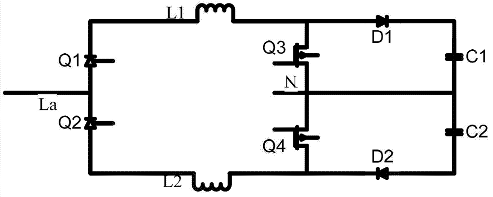
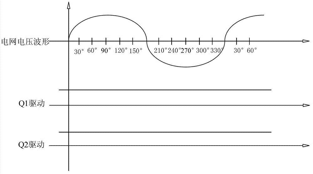
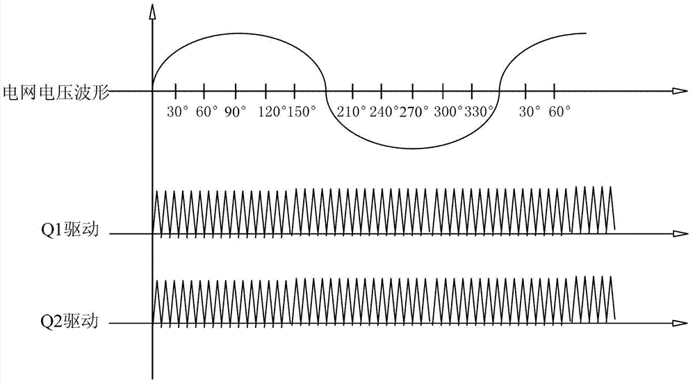
[0055] In the prior art, when the commercial power is working normally, the driving device for the thyristor generally continuously outputs driving signals to the first thyristor Q1 and the second thyristor Q2, and these two thyristors are used as diodes. from the aforementioned figure 1From the working principle of the dual BOOST circuit shown, it can be seen that the first thyristor Q1 needs to be turned on in the positive half cycle of the grid voltage AC, and the second thyristor Q2 needs to be turned on in the negative half cycle of the grid voltage AC. According to the reverse voltage isolation characteristics of thyristors, theoretically, in the prior art, the driving of the first thyristor Q1 and the second thyristor Q2 is continuously turned on. In the positive half cycle of the grid voltage AC, the second thyristor Q2 will be closed due to the negative voltage applied to both ends. Turn off, in the negative half cycle of the grid voltage AC, the first thyristor Q1 is...


PUM


Abstract

The invention discloses a silicon controlled rectifier driving method and a silicon controlled rectifier driving device. The method comprises the steps that the load value of a circuit on which a silicon controlled rectifier is positioned, and a plurality of phase angles are determined according to the load value; the plurality of phase angles are positioned in a phase angle zone corresponding to the silicon controlled rectifier; the number of the plurality of phase angles is in inverse correlation with the load value; and a driving signal output time section corresponding to each phase angle in the plurality of phase angles outputs driving signals to a silicon controlled rectifier needing to be driven at present. According to the silicon controlled rectifier driving method, the driving loss of the silicon controlled rectifier can be lowered.

Description

technical field [0001] The present application relates to the field of circuits, in particular to a method and device for driving a thyristor. Background technique [0002] The thyristor (SCR) has the following characteristics: 1) The driver can only turn on the cathode and anode (AK pole) of the thyristor, but cannot turn it off, and the thyristor can only be turned off by reducing the current of its own AK pole to 0; 2) When there is In the case of driving, the thyristor is equivalent to a diode, which has forward conduction and negative shutoff performance, and can block the reverse voltage. [0003] In the field of high-frequency rectification, the dual BOOST topology is widely used in medium-power rectifiers because it is compatible with both DC and AC input. figure 1 It is a schematic diagram of the dual BOOST circuit structure. The working principle of the circuit is: the grid voltage AC is rectified by the first thyristor Q1 and the second thyristor Q2. When the gri...

Claims


Application Information

Patent Timeline
IPC IPC(8): H02M1/06
Inventor 黄朱勇杜坤
Owner HUAWEI DIGITAL POWER TECH CO LTD
Why Eureka
Try Eureka