Offset calibration and precision hysteresis for a rail-rail comparator with large dynamic range

A rail-to-rail and offset calibration technology, which is applied to amplifiers, amplifiers, and differential amplifiers with semiconductor devices/discharge tubes, and can solve problems such as complicating comparators

Active Publication Date: 2012-11-14
MICROCHIP TECH INC
View PDF3 Cites 9 Cited by
  • Summary
  • Abstract
  • Description
  • Claims
  • Application Information

AI Technical Summary

Problems solved by technology

This requirement complicates adding precision hysteresis to the rail-to-rail comparator since the Gm (transconductance) of the rail-to-rail comparator input stage varies with the input common-mode voltage

Method used


Image

  • Offset calibration and precision hysteresis for a rail-rail comparator with large dynamic range
  • Offset calibration and precision hysteresis for a rail-rail comparator with large dynamic range
  • Offset calibration and precision hysteresis for a rail-rail comparator with large dynamic range

Examples


Embodiment Construction

[0014] Referring now to the drawings, details of certain exemplary embodiments are schematically illustrated. Like elements in the drawings will be represented by the same numerals, and similar elements will be represented by the same numerals with different lowercase letter suffixes.

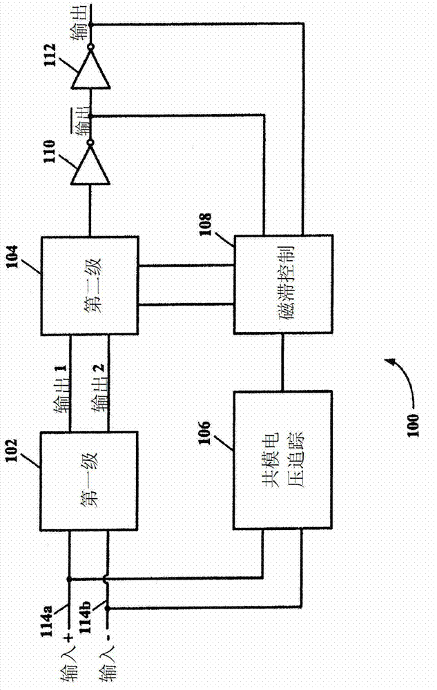
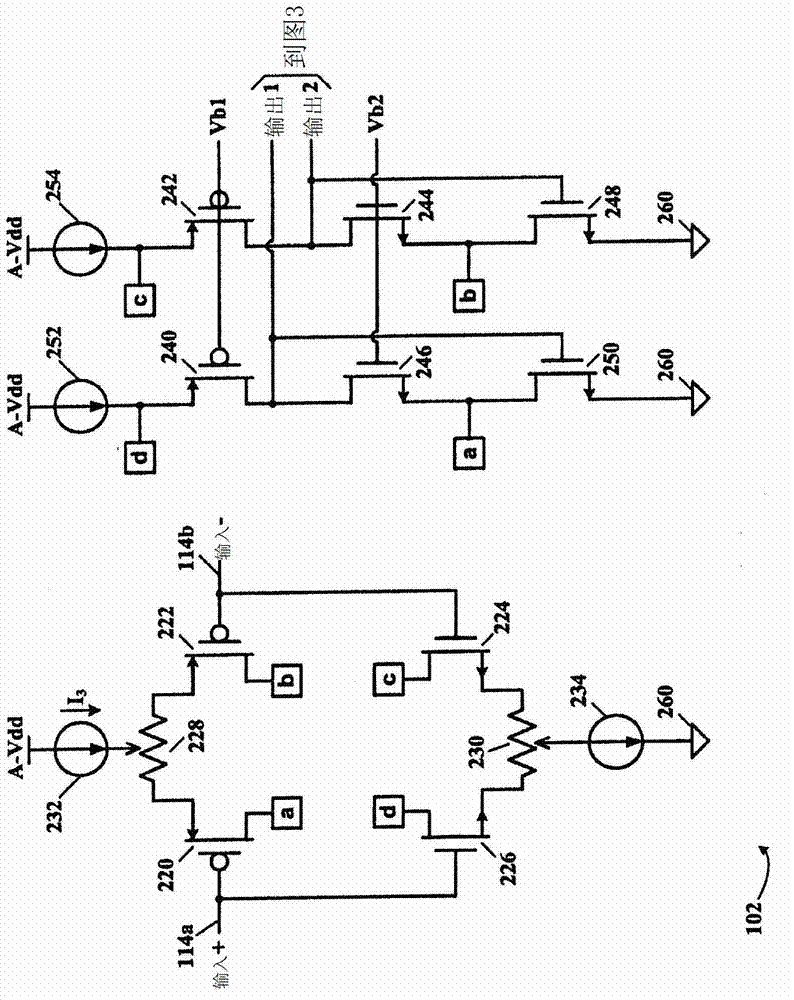
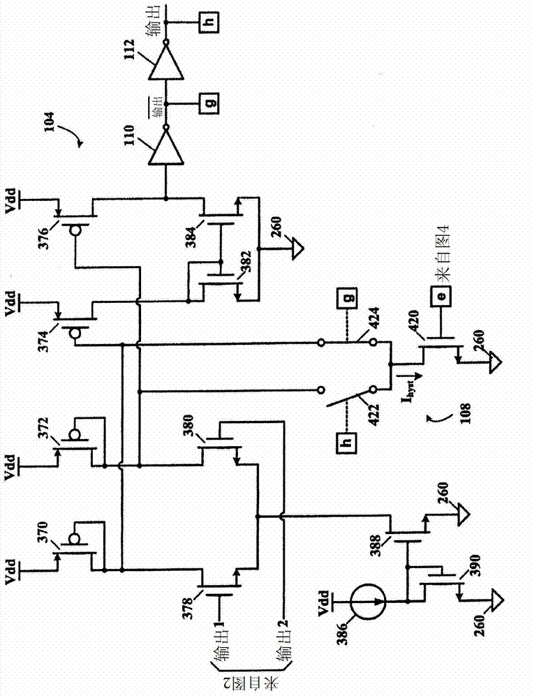
[0015] refer to figure 1 , which depicts a schematic block diagram of a two-stage rail-to-rail comparator according to certain exemplary embodiments of the present invention. A two-stage rail-to-rail comparator generally indicated by numeral 100 includes: a first stage 102 , a second stage 104 , a common mode voltage tracking circuit 106 and a hysteresis control 108 . The first stage 102 has a differential input 114 connected to a differential input pair feeding current to a diode-connected load ( figure 2 ). Second stage 104 receives the differential output signal (Output 1 and Output 2 ) from first stage 102 and amplifies this output signal sufficiently to drive inverting gate 110 , which...


PUM


Abstract

A rail-rail comparator having an input stage with independent positive and negative differential voltage offset compensation tracks changes in Gm (transconductance) of the input stage. By tracking the changes in Gm (transconductance) of the input stage, hysteresis of the rail-rail comparator becomes insensitive to the input common mode voltage. A two-stage rail-rail comparator may be used for adding hysteresis to a second stage. The first stage of the two-stage rail-rail comparator operates at substantially unity gain. The second stage of the two-stage rail-rail comparator operates as a regular high gain amplifier with hysteresis. Additional circuitry tracks the Gm (transconductance) change of the first stage to make the second stage hysteresis insensitive to the input common mode voltage at the first stage.; This also makes it easier to create a programmable hysteresis that is accurate over all input voltage values.

Description

technical field [0001] The present invention relates to rail-to-rail comparators, and more particularly, the present invention relates to offset calibration and precision hysteresis for rail-to-rail comparators with large dynamic range. Background technique [0002] A rail-to-rail comparator input stage has two types of differential pairs that must be offset calibrated separately. This requirement complicates the addition of precision hysteresis to rail-to-rail comparators because the Gm (transconductance) of the rail-to-rail comparator input stage varies with the input common-mode voltage. Since the hysteresis voltage becomes a variable, especially when the input common mode voltage is near the middle of the voltage rails, the hysteresis becomes half the value near either rail (eg, Vdd or common (ground)). Contents of the invention [0003] The above problems are solved and other and further benefits are realized by tracking the change in Gm (transconductance) of the rai...

Claims


Application Information

Patent Timeline
Patent Type & Authority Applications(China)
IPC IPC(8): H03K3/3565H03F3/45
CPCH03K3/3565H03F3/45699H03F3/45H03F3/45479H03F3/45632H03F3/45695H03K5/22
Inventor 阿尼鲁达·巴沙尔
Owner MICROCHIP TECH INC
Why Eureka
Try Eureka