
Corn threshing machine

A technology for thresher and corn, applied in threshing equipment, agricultural machinery and implements, application and other directions, can solve the problems of low working efficiency of corn thresher, difficult to improve working efficiency, etc., and achieve convenient and fast input, simple structure and high working efficiency. Effect

Inactive Publication Date: 2012-11-21
桓仁弘兴农机制造有限公司
View PDF7 Cites 14 Cited by
  • Summary
  • Abstract
  • Description
  • Claims
  • Application Information

AI Technical Summary

Problems solved by technology

Although this corn thresher can solve problems such as difficult operation, because this kind of corn thresher can only force the corn kernels to fall off under the action of the rectangular teeth on the two straight sides of the corn input cylinder, and the corn ears are also input by axial input. The corn thresher has the problem that the subsequent corn ears can be vertically input into the corn input barrel after the front corn cob is discharged, so the working efficiency of the corn thresher is relatively low. Even if the design of the automatic control device is reasonable, it is not easy to improve work efficiency

Method used


Image

  • Corn threshing machine
  • Corn threshing machine
  • Corn threshing machine

Examples


Embodiment 1

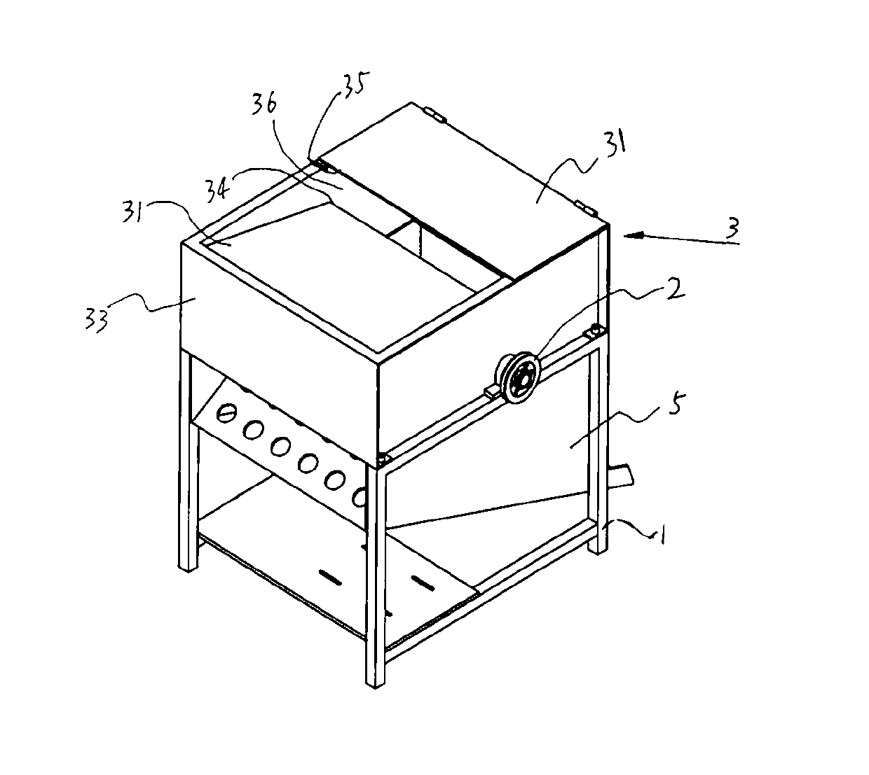
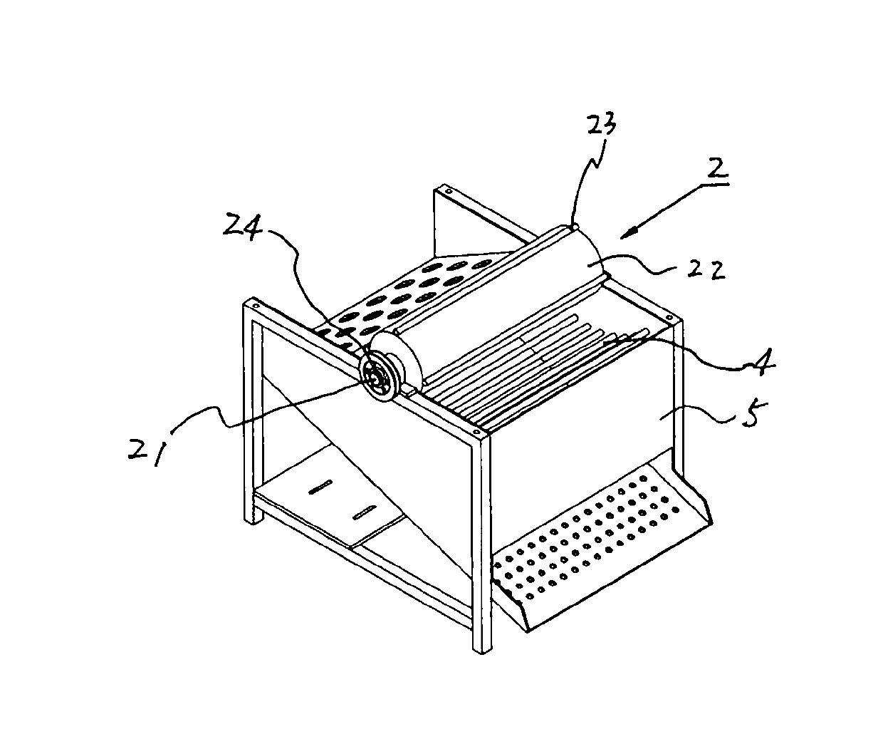
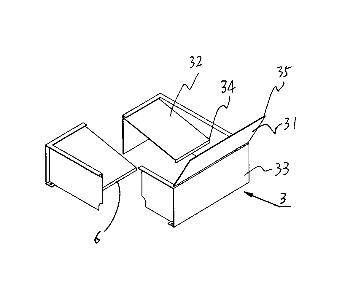
[0019] see Figure 1 to Figure 3 , these three drawings provide the overall structure of the appearance of an embodiment of the corn thresher proposed by the present invention. The threshing machine includes a frame 1 , a threshing cylinder 2 , a corn feeding assembly 3 , an arc-shaped limiting screen 4 , a material conveying assembly 5 and a limiting member 6 .

[0020] The threshing cylinder 2 is installed on the top of the frame 1, and it is composed of a grained rod cylinder. The grained rod cylinder includes a cylinder 22 limited by a rotating shaft 21 and a strip-shaped rib 23 axially arranged on the cylinder 22. There are 6 shaped ribs 23, and two adjacent strip shaped ribs 23 are radially spaced at equal distances. The strip-shaped ribs 23 are parts used for removing corn kernels, the number of which can be determined according to the diameter of the cylinder 22, usually 2-6 strip-shaped ribs 23 can be set, and the strip-shaped ribs 23 can be straight rods , can ...

Embodiment 2

[0026] see Figure 5 and Image 6 , these two drawings provide the appearance structure of another embodiment of the corn thresher proposed by the present invention. The threshing machine also includes a frame 1 , a threshing cylinder 2 , a corn feeding assembly 3 , an arc-shaped limiting screen 4 , a feeding assembly 5 and a limiting member 6 . The structures of the frame 1, the threshing drum 2, and the arc-shaped limit screen 4 are basically the same as those of the embodiment 1, and will not be described in detail in this embodiment.

[0027] The corn feeding assembly is installed on the top of the frame 1, which includes a frame 3 made of plates, the frame 3 is a rectangular base 31 made of three vertical plates, and the top of the base 31 is provided with a frame made of plates. The cross-section is V-shaped and is arranged on the shading plate 33 opposite to the corn feeding portion 32, and the end portion of the corn feeding portion 32 and the end portion of the...


PUM


Abstract

The invention relates to a corn threshing machine. A corn feeding assembly is installed above a threshing drum; an arc-shaped limiting sieve is installed below the threshing drum; and a limiting component for limiting position of a corncob in a threshing process is arranged between the corn feeding assembly and the threshing drum. The corn threshing machine can continuously feed the corncobs from the corn feeding assembly into the threshing drum and quickly thresh the corncobs and has a very high working efficiency.

Description

technical field [0001] The invention relates to a corn thresher, in particular to a corn thresher composed of a threshing drum driven by a power device installed on a frame. Background technique [0002] The corn thresher in the prior art generally includes a threshing drum driven by a power unit, a corn input cylinder installed above the threshing drum, and an arc-shaped limit screen installed below the threshing drum. The shape of the inner surface of the corn input cylinder is similar to that of the outer surface of the threshing drum, and the corn input cylinder adopts a long structure. After the corn is input into it along the axial direction of the corn input cylinder, the diameter of the corn is different, so A plate is also installed in the corn input cylinder, and an adjustment bolt is installed on the top of the plate, so that the input corn is close to the threshing drum, forcing the ear of corn to thresh when the threshing drum rotates. The first problem of this...

Claims


Application Information

Patent Timeline
IPC IPC(8): A01F12/20
Inventor 肖兴安
Owner 桓仁弘兴农机制造有限公司
Learn More