Design method for baffle plate used for controlling film thickness distribution on conical optical element in film plating planetary system

An optical element and planetary system technology, which is applied in the field of baffle design for controlling the film thickness distribution of conical optical elements, can solve the problems of difficult analytical solutions for baffles, requiring several or even a dozen experiments, and complex projection trajectories.

Active Publication Date: 2012-11-21
INST OF OPTICS & ELECTRONICS - CHINESE ACAD OF SCI
View PDF2 Cites 5 Cited by
  • Summary
  • Abstract
  • Description
  • Claims
  • Application Information

AI Technical Summary

Problems solved by technology

[0005] As far as the planetary system of the vacuum coating machine is concerned, since the planetary revolution/rotation can be flexibly adjusted, the randomness of the position of any point on the coating surface of the conical optical element is very high, so that any point on the coating surface of the conical optical element is closely related to the evaporation or sputtering source. The projection trajectory of the line connecting any point on the surface on the plane where the baffle is placed is very complicat

Method used


Image

  • Design method for baffle plate used for controlling film thickness distribution on conical optical element in film plating planetary system
  • Design method for baffle plate used for controlling film thickness distribution on conical optical element in film plating planetary system
  • Design method for baffle plate used for controlling film thickness distribution on conical optical element in film plating planetary system

Examples


Embodiment Construction

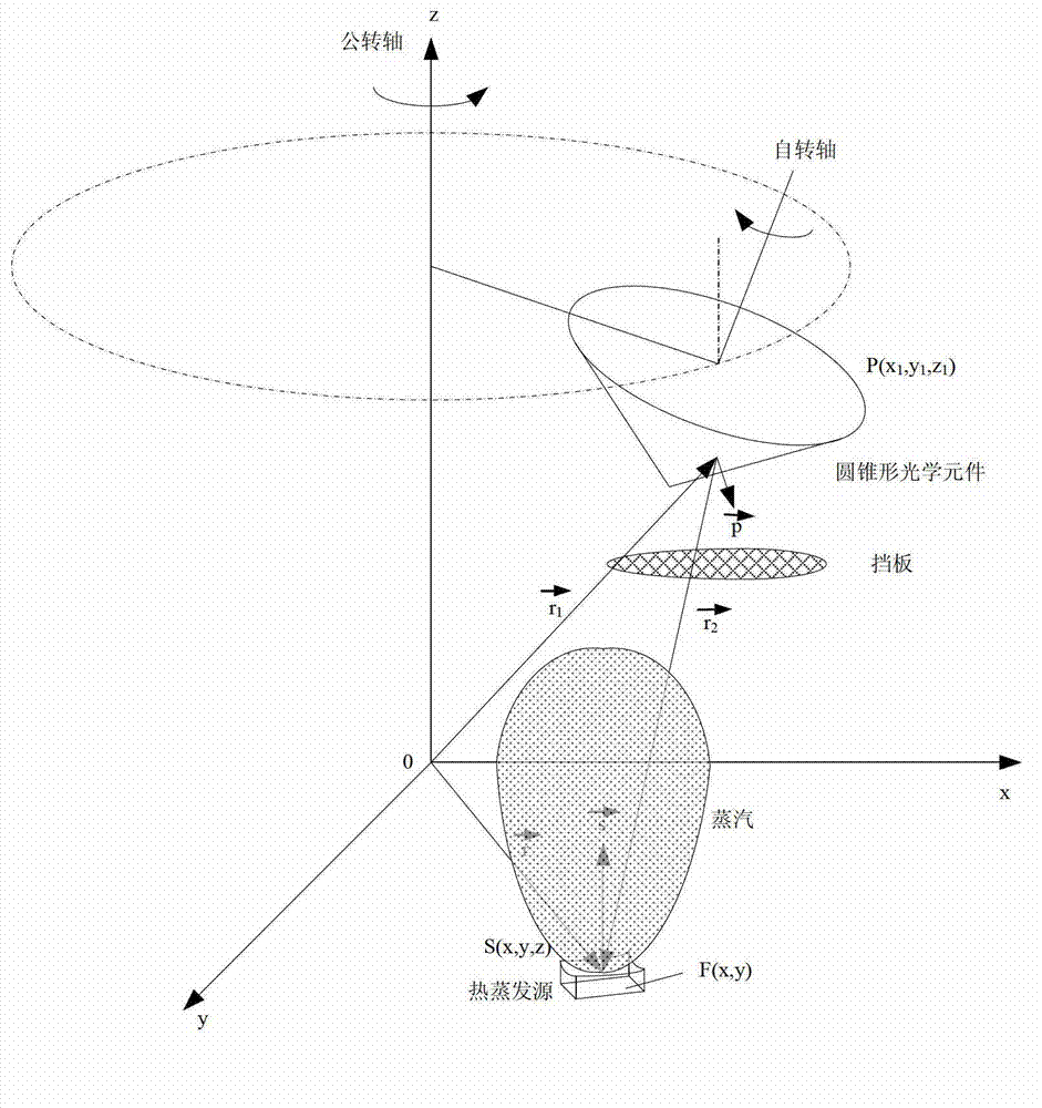
[0024] Such as figure 1 Shown is a schematic diagram of the thermal evaporation source-optical element-baffle combination system in a thermal evaporation vacuum coater equipped with a planetary system. In the thermal evaporation vacuum coating process, the evaporated thin film material is transported in a vacuum environment and deposited on the coating surface of the conical optical element to form a thin film. In order to make the conical optical thin film element meet the performance requirements of the optical system, it is necessary to control the film thickness distribution on the conical optical element in the planetary system of the vacuum coating machine. The most common approach is to use baffles to control the film thickness distribution. The coating surface of the conical optical element can be convex or concave. The specific computer optimization design process of the baffle used to control the film thickness distribution on the conical optical element in the pla...


PUM


Abstract

The invention provides a design method for a baffle plate used for controlling film thickness distribution on a conical optical element in a film plating planetary system. According to the invention, in the process of vacuum plating, a film material is transmitted in a vacuum environment in a manner of evaporation or sputtering and forms a film with nonuniformly distributed thickness on the surface of the conical optical element, a film thickness distribution model capable of reflecting actual thickness distribution of the film deposited on the conical optical element in a vacuum plating machine planetary system when the baffle plate is not used and a film thickness distribution model capable of reflecting actual thickness distribution of the film on the conical optical element when baffle plate correction is used are respectively established; evaporation or sputtering characteristics of the film material during vacuum plating are determined based on the film thickness distribution model when the baffle plate is not used, then film thickness distribution on the conical optical element is simulated by using theories for the film thickness distribution model when baffle plate correction is used, designing of the baffle plate is optimized by using a computer until film thickness distribution on the conical optical element in the vacuum plating machine planetary system meets design demands after utilization of baffle plate correction, and therefore, an optimal baffle plate design is obtained. The method provided by the invention can realize accurate control of film thickness distribution on the conical optical element.

Description

technical field [0001] The invention relates to the field of optical thin film element preparation, in particular to a baffle design method for controlling the film thickness distribution of a conical optical element in a coating planetary system. Background technique [0002] With the development of science and technology, the design of optical system is becoming more and more sophisticated. In order to meet the performance index of the optical system, conical optical elements are used in some optical systems, and a specially designed optical film is coated on the surface of the conical optical element to improve the performance of the conical optical element. The current techniques for preparing optical thin films on conical optical elements can be mainly divided into physical vapor deposition (PVD) and chemical vapor deposition (CVD). Physical vapor deposition is a process in which a thin film is deposited on the surface of a conical optical element by evaporating or spu...

Claims


Application Information

Patent Timeline
IPC IPC(8): C23C14/54
Inventor 李斌成郭春孔明东柳存定
Owner INST OF OPTICS & ELECTRONICS - CHINESE ACAD OF SCI
Why Eureka
Try Eureka