Display Device

A display device and display panel technology, which is applied in the direction of identification devices, optics, instruments, etc., can solve the problems of reducing thickness, difficulty maintaining strength, repairing display panels, etc., and achieve the effect of reducing thickness and maintaining strength

Inactive Publication Date: 2012-11-21
SONY CORP
View PDF8 Cites 0 Cited by
  • Summary
  • Abstract
  • Description
  • Claims
  • Application Information

AI Technical Summary

Problems solved by technology

In this sense, self-luminous display panels can reduce thickness; however, it is difficult to maintain strength as a product, which is a problem in commercialization
[0004] Although the strength can be maintained by fixing the display panel with double-sided tape or adhesive, etc., when a problem occurs, it is difficult to repair the display panel by removing the double-sided tape or adhesive, and in this method, even Is a small defect, also had to replace the entire display panel

Method used


Image

  • Display Device
  • Display Device
  • Display Device

Examples


no. 1 example

[0034] [Components of Display Device 1 ]

[0035] (overall structure)

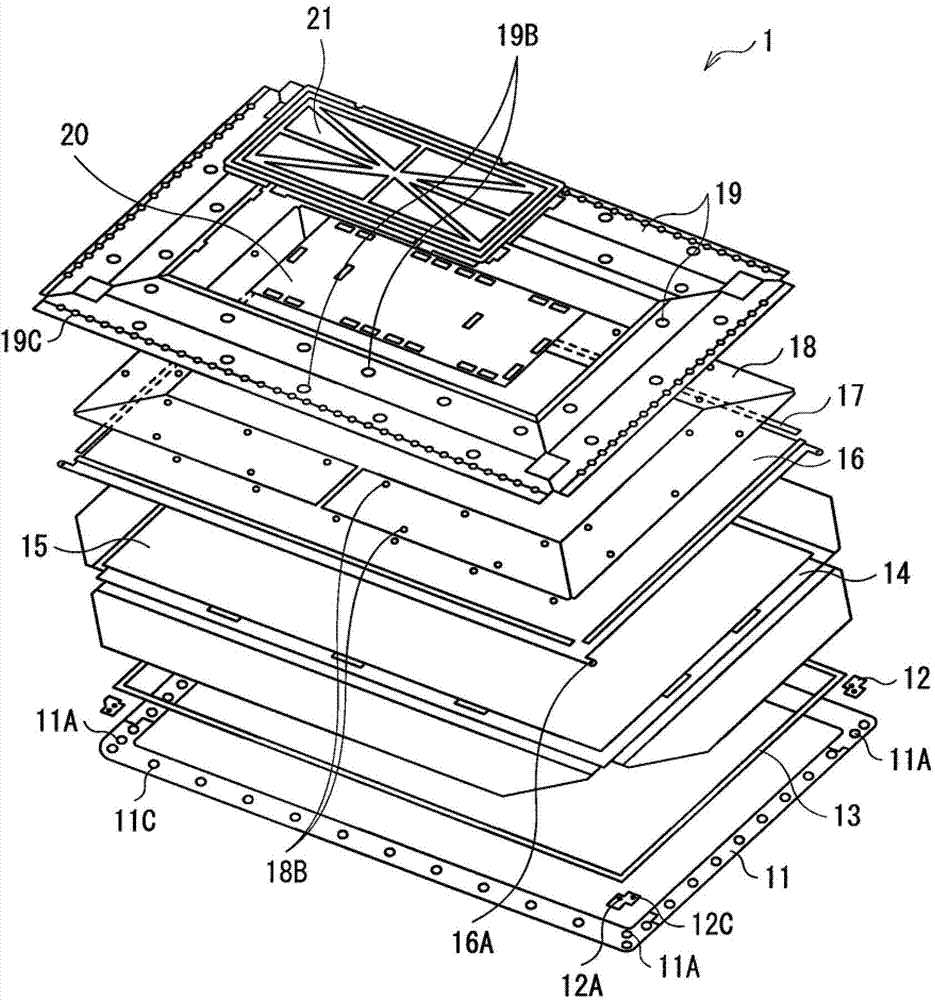
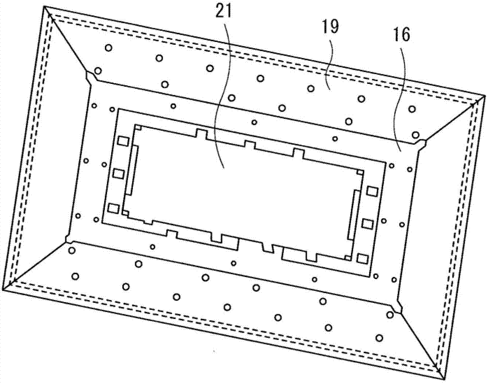
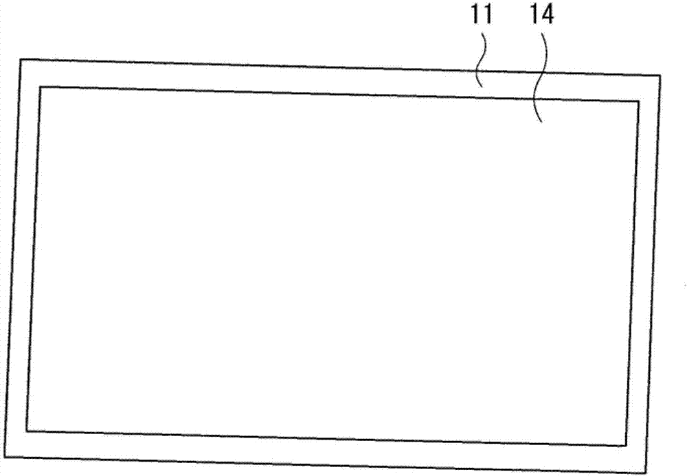
[0036] figure 1 The layer configuration of the display device (display device 1 ) according to the first embodiment of the present technology is shown. Figure 2A is a top view of the back side of the display device 1, and Figure 2B It is a plan view of the display surface side of the display device 1 . In display device 1 , front support member 11 , panel spacer 13 , display panel 14 , graphite sheet 15 , bottom plate 16 , heat radiation sheet 17 , insulating sheet 18 , and rear support member 19 are provided in this order from the display surface. Panel guides 12 are arranged at corners of the front support member 11 .

[0037] Such as image 3 As shown, the display panel 14 is composed of a display unit 141 , a chip on film (COF, chip on film) 142 and a driver substrate 143 . The display device 1 of the present embodiment is an organic EL display device, and a plurality of organic EL elements are...

no. 2 example

[0087] Figure 14A with Figure 14B The configuration of the back support member (back support member 19 - 1 ) of the display device (display device 2 ) according to the second embodiment of the present disclosure is shown. Figure 14B to show Figure 14A Magnified view of the area enclosed by the dashed line. The back support member 19-1 has the shape of a rectangular plate, and is provided with a hook portion 19F at its periphery. In this example, although two hooks 19F are provided at the long sides of the rectangle, the number and positions of the hooks 19F are not limited thereto. Other than that, this display device has a configuration similar to that of the display device 1 of the above-described embodiment, and its functions and effects are also similar to those of the display device 1 of the above-described embodiment.

[0088] The hook portion 19F has a hook-like shape in which a part of the end portion of the back support member 19 - 1 is bent in the vertical di...


PUM

PropertyMeasurementUnit
Thicknessaaaaaaaaaa

Abstract

A display device includes: a base plate being provided on a first side of a display panel; a front-face supporting member facing the base plate with the display panel therebetween, having a periphery on an external side with respect to the display panel, and being joined to the base plate at part or all of a peripheral portion of the front-face supporting member; and a back-face supporting member facing the front-face supporting member with the base plate therebetween, and being joined to both of the front-face supporting member and the base plate at a peripheral portion of the back-face supporting member.

Description

technical field [0001] The present technology relates to a display device applied to a thin display or the like. Background technique [0002] In recent years, thin displays often employ a liquid crystal panel (LCD) or a plasma display panel (PDP) as a display panel (for example, see Japanese Unexamined Patent Application Publication No. 2008-58860). On the other hand, as a next-generation display panel, commercialization of a self-luminous display panel using organic EL (electroluminescence) or the like has been studied. [0003] However, under the current situation, it is difficult to commercialize a large display device of the self-luminous type, for example, having a size of 32 inches or more. Unlike a liquid crystal panel or the like which is generally contained in a casing together with a backlight unit (BLU) when commercialized, a self-luminous display panel does not necessarily use a backlight unit. In this sense, the self-luminous display panel can reduce the thic...

Claims


Application Information

Patent Timeline
IPC IPC(8): G09F9/33
CPCG02F2201/503G02F2201/46G02F1/133308G02F2001/133322G02F2001/133314G02F2001/13332G02F1/133382G02F2001/133317H05K5/02G02F1/13452G02F1/13332G02F1/133322G02F1/133317G02F1/133314
Inventor 高岛秀利伊藤启宣
Owner SONY CORP
Why Eureka
Try Eureka