Device for controlling a fluid flow

A technology for controlling fluids and manipulating devices, which is applied in packaging, liquid materials, transportation and packaging, etc. It can solve the problems of affecting the direction of overflow, the influence of geometry that cannot overflow, and the phenomenon of product spraying that cannot be reliably avoided, so as to reduce foam. Effect

Inactive Publication Date: 2012-11-21
SIG TECH AG
View PDF6 Cites 1 Cited by
  • Summary
  • Abstract
  • Description
  • Claims
  • Application Information

AI Technical Summary

Problems solved by technology

[0004] The phenomenon of product spraying during the filling process and undesired, sometimes uncontrollable and irreproducible lateral deflections of the overflowing product flow cannot be reliably avoided when using rotary slide valves
[0005] It is generally regarded as a disadvantage of the known metering elements that the overflow geometry of the product flow emerging from the metering element cannot be influenced in a targeted manner and in particular the overflow direction cannot be influenced in a suitable manner.

Method used


Image

  • Device for controlling a fluid flow
  • Device for controlling a fluid flow
  • Device for controlling a fluid flow

Examples


Embodiment Construction

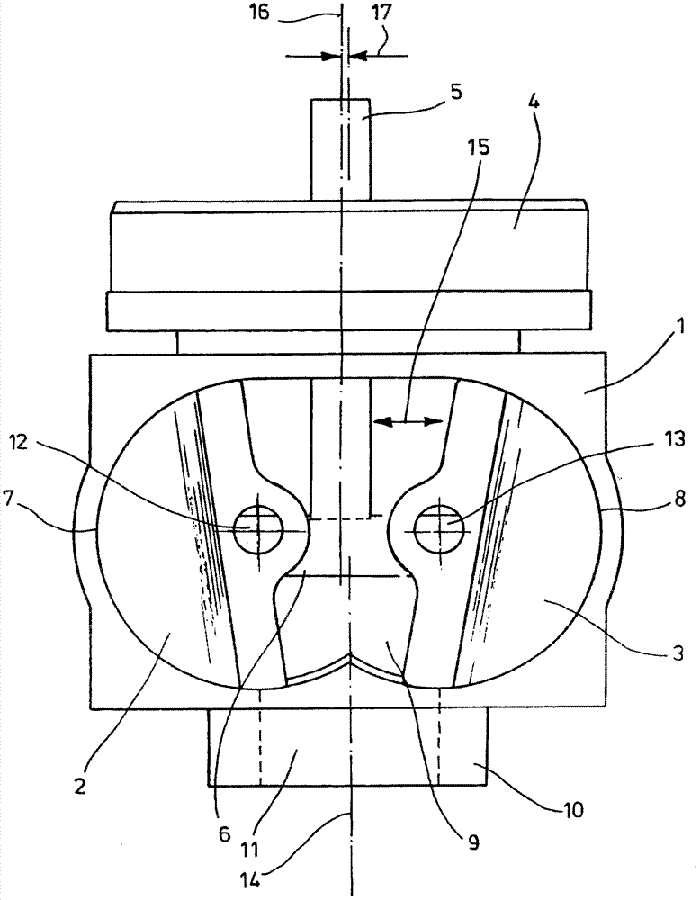
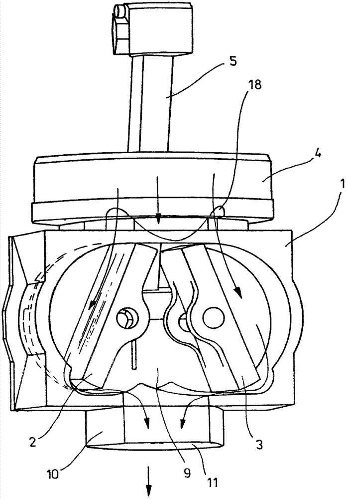
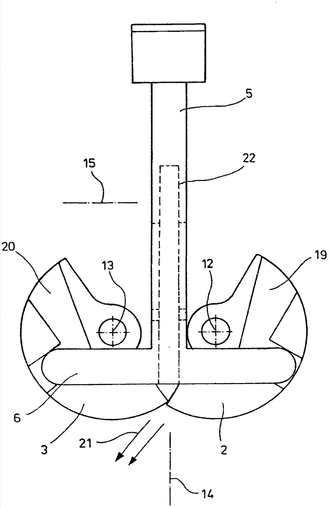
[0025] in accordance with figure 1 In the embodiment shown, two valve elements 2 , 3 are arranged in the housing 1 . The housing 1 has a cover 4 through which an actuating element 5 can be guided. In the exemplary embodiment shown, the actuating element 5 is configured in the form of a rod and is provided with a transverse web 6 in the region of its end facing the valve elements 2 , 3 . The transverse web 6 transmits the movement of the actuating element 5 to the valve elements 2 , 3 and predetermines its positioning relative to the housing 1 .

[0026] In particular, it is contemplated that the actuating element 5 can be arranged at least in regions or also completely inside the packing and thus protect it from contact with the external environment. Such an arrangement is particularly advantageous for sterile or aseptic filling processes, since contamination by germs, molds or microorganisms can thereby be avoided. The actuating element 5 arranged completely inside the fil...


PUM


Abstract

The invention relates to a device for controlling a fluid flow and comprising a housing and two valve elements arranged inside an inner chamber of the housing. The valve elements are movably arranged relative to the housing and are connected to an actuating device. The first valve element is designed to perform a first motion process, and the second valve element is designed to perform a second motion process. The first motion process and the second motion process can be varied by the actuating device.

Description

technical field [0001] The invention relates to a device for controlling the flow of a fluid, which device has a housing and two valve elements arranged in the inner space of the housing, the valve elements are arranged movably relative to the housing and are connected to the operating device connect. Background technique [0002] Such devices are used, for example, to fill containers with liquids, especially beverages. The device can also be used to meter liquids containing solid or agglomerated constituents. The opening and closing process is more typically controlled by the use of piston or rotary slide valves. [0003] However, both the use of corresponding pistons and the use of rotary slide valves entail certain disadvantages. In particular in the case of piston valves, the disadvantage is that when the valve is closed, the narrowed cross-sectional area leads to a violent escape of the jet of filling fluid and thus to spraying of the filled product or the generation...

Claims


Application Information

Patent Timeline
Patent Type & Authority Applications(China)
IPC IPC(8): B65B37/20B65B39/00B65B3/30
CPCB65B3/30B65B37/20B65B39/003
Inventor C·梅勒
Owner SIG TECH AG
Why Eureka
Try Eureka