Vehicle control device

A technology for control devices and vehicles, which is applied in electrical control, power devices, exhaust devices, etc., and can solve problems such as decreased insulation resistance, inability to EHC, and energization.

Inactive Publication Date: 2012-11-21
TOYOTA JIDOSHA KK
View PDF5 Cites 10 Cited by
  • Summary
  • Abstract
  • Description
  • Claims
  • Application Information

AI Technical Summary

Problems solved by technology

In this situation, in order to warm up the catalyst, it is preferable to energize the EHC, but there is a possibility that the EHC cannot be energized due to the decrease in insulation resistance caused by the high temperature of the holding mat as described above.

Method used


Image

  • Vehicle control device
  • Vehicle control device
  • Vehicle control device

Examples


no. 1 approach

[0070] In the first embodiment, when the deceleration F / C condition is satisfied, the ECU 70 prohibits the execution of the F / C during deceleration to maintain the holding mat temperature at a temperature lower than the EHC bed temperature. That is, in the first embodiment, the execution of F / C at the time of deceleration is prohibited, and combustion is performed in the engine 1 to supply the combusted gas to the EHC 13 , thereby suppressing the supply of gas generated by the F / C to the EHC 13 . cold air.

[0071] More specifically, when the deceleration F / C condition is satisfied, the ECU 70 prohibits execution of the above-mentioned F / C when the temperature obtained by adding a predetermined temperature to the holding pad temperature is equal to or higher than the EHC bed temperature. That is, the execution of F / C during deceleration is prohibited only when the relationship of "retaining mat temperature + specified temperature ≥ EHC bed temperature" is established, and when...

no. 2 approach

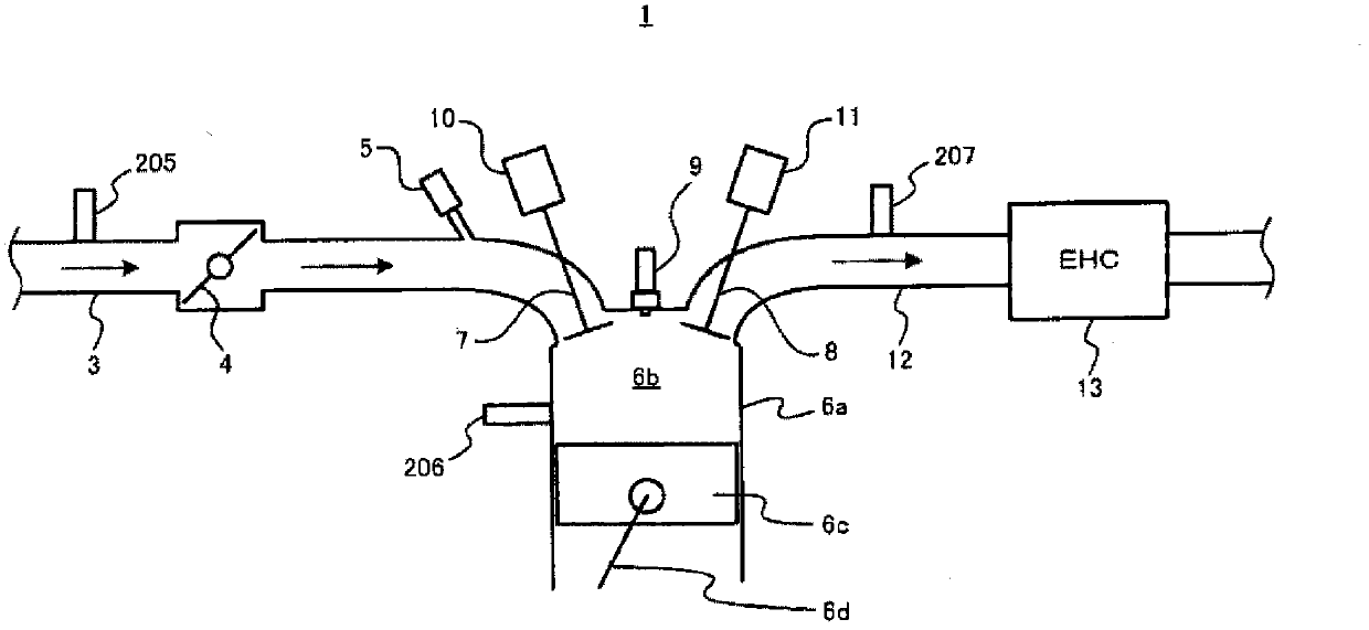
[0084] Next, a second embodiment will be described. In the second embodiment, when the deceleration F / C condition is satisfied, when the temperature obtained by adding a predetermined temperature to the holding pad temperature is equal to or higher than the EHC bed temperature, the intake valve 7 is closed and the F / C is executed. The control of the exhaust valve 8 is different from the first embodiment in this point. That is, in the second embodiment, the execution of F / C during deceleration is not prohibited, and the control of setting the intake valve 7 and the exhaust valve 8 to fully close (in other words, making the intake valve 8 fully closed) is performed during execution of F / C. valve 7 and exhaust valve 8 stop control). Specifically, in the second embodiment, the intake valve 7 and the exhaust valve 8 are forcibly set fully closed during execution of F / C, thereby blocking the flow of gas from the engine 1 to the EHC 13 when F / C is generated. The supply of cold air ...

no. 3 approach

[0092] Next, a third embodiment will be described. In the third embodiment, when the deceleration F / C condition is satisfied, when the temperature obtained by adding a predetermined temperature to the holding pad temperature is equal to or higher than the EHC bed temperature, the throttle valve 4 is controlled to be closed when F / C is executed. (hereinafter referred to as "throttle closing control"), this point is different from the first embodiment and the second embodiment. That is, in the third embodiment, the execution of the F / C is not prohibited during deceleration as in the second embodiment, but when the F / C is executed, instead of the control to close the intake valve 7 and the exhaust valve 8, the throttling is performed. Valve closing control is different from the second embodiment in this point. Specifically, in the third embodiment, throttle closing control is performed when F / C is executed, thereby reducing the amount of other supply generated when F / C is direct...


PUM


Abstract

Disclosed is a vehicle control device for application in a vehicle having an internal combustion engine and an electrically heated catalyst that can be warmed by the application of an electric current. The catalyst is equipped with a catalyst support for supporting the catalyst, and a support holding unit - which has electrically insulative properties - for holding the catalyst support. The vehicle control device is provided with a control means, which, when conditions are met for execution of a fuel cut of the internal combustion engine during deceleration, controls by suppressing the supply of uncombusted gas from the internal combustion engine to the electrically heated catalyst in order to keep the temperature of the support holding unit below the temperature of the catalyst. As a result, it is possible to minimize sudden cooling of the catalyst, and also possible to keep the temperature of the support holding unit below the temperature of the catalyst.

Description

technical field [0001] The present invention relates to a control device for a vehicle including an electrically heated catalyst in an exhaust passage. Background technique [0002] Conventionally, a technique for purifying exhaust gas using an electrically heated catalyst (hereinafter appropriately referred to as "EHC (Electrically Heated Catalyst)") arranged in an exhaust passage is known. For example, Patent Document 1 describes an EHC in which an electrically insulating material is interposed between an outer peripheral surface of a catalyst carrier and an inner peripheral surface of a metal cover to provide a cushioning ring-shaped mat-like member. [0003] In addition, hereinafter, the constituent elements supporting the catalyst in the EHC are appropriately referred to as "EHC carriers", and the constituent elements holding the EHC carriers are appropriately referred to as "holding mats". [0004] Patent Document 1: Japanese Patent Application Laid-Open No. 5-269387 ...

Claims


Application Information

Patent Timeline
Patent Type & Authority Applications(China)
IPC IPC(8): F01N3/20F02D29/02F02D41/12
CPCY02T10/6239F02D13/0261F02D2200/0802B60K6/445F02D41/021F01N3/2026F02D29/02F01N2590/11F02D41/0235F01N2410/03F02D13/0215F01N2430/10Y02T10/26F01N3/2013F02D41/123Y02A50/20Y02T10/12Y02T10/62
Inventor 吉冈卫熊谷典昭高木直也
Owner TOYOTA JIDOSHA KK
Why Eureka
Try Eureka