Method and system for characterizing and visualizing electromagnetic tracking errors

A tracking system, electromagnetic technology, applied in the field of electromagnetic tracking system, can solve problems such as difficult application, calibration and measurement

Active Publication Date: 2012-11-21
KONINKLIJKE PHILIPS ELECTRONICS NV
View PDF2 Cites 17 Cited by
  • Summary
  • Abstract
  • Description
  • Claims
  • Application Information

AI Technical Summary

Problems solved by technology

However, the clinical environment changes dynamically during the procedure, making pre-procedural calibration measurements difficult to apply during the procedure

Method used


Image

  • Method and system for characterizing and visualizing electromagnetic tracking errors
  • Method and system for characterizing and visualizing electromagnetic tracking errors
  • Method and system for characterizing and visualizing electromagnetic tracking errors

Examples


Embodiment Construction

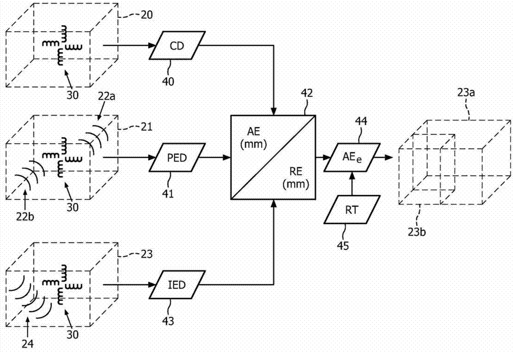
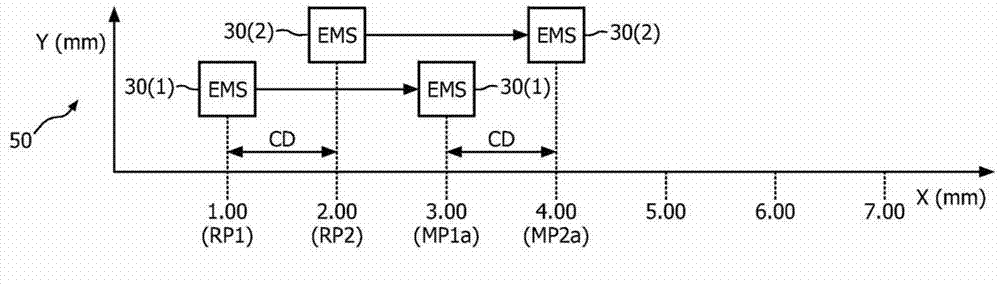
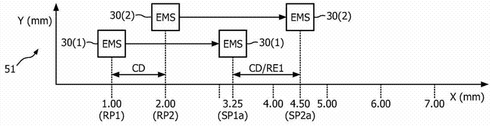
[0025] One definition of the absolute error of an electromagnetic sensor used in the art is the registration error between the tracking of the electromagnetic sensor and a reference navigation system (such as an automatic control device (robot) or an optical tracking system). The present invention is premised on the measurement of the relative error between two (2) electromagnetic sensors with relative absolute errors. figure 1 -3 illustrates an exemplary measurement of relative error in order to understand the concept of relative error according to the present invention.

[0026] specifically, figure 1 Shows a volume 20 of space surrounding an undistorted calibration electromagnetic field (not shown for clarity purposes), a space surrounding a distorted pre-operation electromagnetic field (not shown for clarity purposes) as evidenced by electromagnetic waves 22a and 22b The volume 21, and the volume 23 of space surrounding the distorted operating electromagnetic field (not shown ...


PUM


Abstract

A calibration/surgical tool (90, 160) includes an electromagnetic sensor array (30) of two or more electromagnetic sensors in a known geometrical configuration. Electromagnetic tracking errors are characterized by a mapping of pre-operative absolute and relative errors based on a movement of a calibrated calibration/surgical tool (90, 160) through a pre not operative electromagnetic field. Using statistical mapping, a desired absolute error field (46) is measured either in the clinic as the part of daily quality control checks, or before the patient comes in or in vivo. A resulting error field (46) may be displayed to the physician to provide clear visual feedback about measurement confidence or reliability of localization estimates of the absolute errors in electromagnetic tracking.

Description

Technical field [0001] The present invention generally relates to electromagnetic tracking systems for clinical procedures. The invention specifically relates to the characterization and visualization of electromagnetic tracking errors in an electromagnetic field. Background technique [0002] Electromagnetic tracking systems are often used for real-time guidance of surgical tools in image guided therapy ("IGT") systems. However, the electromagnetic tracking system is very sensitive to electromagnetic field distortion. Due to the presence of ferromagnetic interventional devices or other metal medical instruments, these distortions are caused in the clinical environment. In the presence of field distortion, the electromagnetic tracking measurement results in an uneven and compound error distribution, which affects the physician's ability to accurately and accurately guide surgical tools for treatment delivery. [0003] The ability to quickly characterize and map any potential err...

Claims


Application Information

Patent Timeline
Patent Type & Authority Applications(China)
IPC IPC(8): G06F19/00
CPCA61B2017/00119A61B2019/5251A61B19/5244G06F19/3437A61B34/20A61B2034/2051G16H50/50
Inventor A·K·贾殷M·B·马丁法尔R·陈V·帕尔特阿萨尔蒂D·A·斯坦顿
Owner KONINKLIJKE PHILIPS ELECTRONICS NV
Why Eureka
Try Eureka