Hollow bone grafting type dynamic hip screw

A hip screw, hollow technology, applied in the direction of internal osteosynthesis, medical science, fastening devices, etc., can solve the problems of femoral head necrosis, nonunion, withdrawal, etc., achieve reliable internal fixation, promote early healing, and reduce failure rate Effect

Inactive Publication Date: 2012-11-28
练克俭 +1
View PDF7 Cites 12 Cited by
  • Summary
  • Abstract
  • Description
  • Claims
  • Application Information

AI Technical Summary

Problems solved by technology

However, when using the above-mentioned dynamic hip lag screw fixator to treat femoral neck fractures, there are

Method used


Image

  • Hollow bone grafting type dynamic hip screw
  • Hollow bone grafting type dynamic hip screw
  • Hollow bone grafting type dynamic hip screw

Examples


Embodiment 1

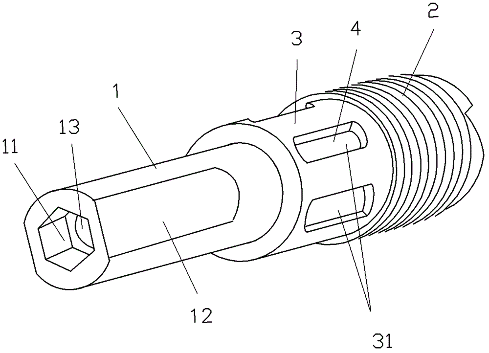
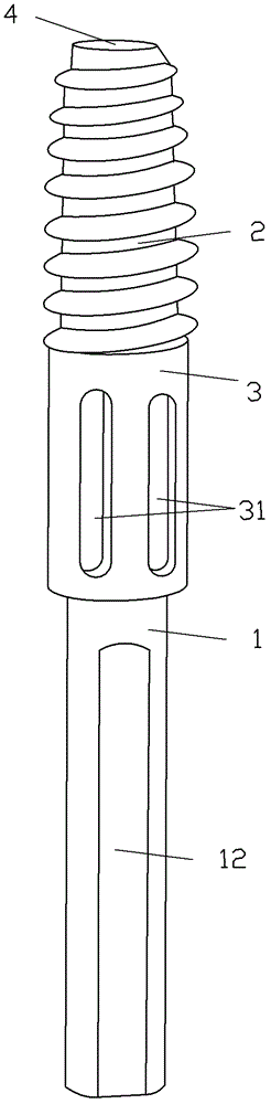
[0021] The three-dimensional structure of a preferred embodiment of the hollow bone graft type dynamic hip screw of the present invention, such as figure 2 and image 3 shown. The hollow bone graft type dynamic hip screw is an improvement of the lag screw used in orthopedic surgery. Its whole body is provided with a guide pin hole 13 penetrating along the central axis, and the front end of the nail body 1 has a bone thread 2; the outer peripheral surface of its circular tubular nail body 1 rear part has two opposite planes 12, so that the nail body 1 rear part The cross-section of the screw is oblate; the rear end of the nail body 1 is provided with an inner hexagon socket 11, which is very convenient for doctors to use a lag screw to insert a driver to rotate the dynamic hip screw during operation. The nail body 1 is provided with a cage-shaped part 3 which is hollow inside and has a plurality of elongated windows 31 extending along the central axis direction on the outer ...

Embodiment 2

[0024] The structure of another preferred embodiment of the hollow bone graft type dynamic hip screw of the present invention, as Figure 6 and Figure 7 shown. The overall length of the hollow bone graft type dynamic hip screw is much smaller than that of the previous embodiment. The whole body of this embodiment is provided with a guide pin hole 130 penetrating along the central axis, and the front end of the nail body 10 has a bone thread 20; the outer peripheral surface of the circular tubular nail body 10 rear part has two opposite planes 120, so that the nail body 10 is The cross-section of the part is oblate; the rear end of the nail body 10 is provided with an inner hexagon socket 110 . The nail body 10 is provided with a cage-shaped portion 30 that is hollow inside and has a plurality of elongated windows 310 extending along the central axis direction on the outer peripheral surface near the bone thread 20 . The cage-like part 30 protrudes outward along the outer p...


PUM


Abstract

The invention discloses a hollow bone grafting type dynamic hip screw, relating to a lag screw for orthopedic surgery. The hollow bone grafting type dynamic hip screw disclosed by the invention is a lag screw, wherein an entire body is provided with a guide pin hole which perforates along the central axis, a bone thread is arranged at the front end of a screw body, and a hollow cage-like part with a window on the outer peripheral surface is arranged at the tail end of the screw body, which is close to the bone thread. Before the dynamic hip screw is locked, autologous bone broken pieces of a patient are placed in the cage-like part. After the dynamic hip screw is locked at the part with a fracture of the neck of the femur of the patient, the pressurization of the fracture end can be completed, and the reliable internal fixation is achieved; and autologous cancellous bone can be also implanted on the surface on the periphery of the fracture end, which is in contact with the screw, and the autologous cancellous bone can penetrate through the window of the cage-like part and is combined with the bone of the neck of the femur, so that early healing of the fracture can be promoted.

Description

technical field [0001] The invention relates to a lag screw for orthopedic surgery. Background technique [0002] Femoral neck fractures have been receiving much attention due to the difficulty of clinical treatment, and they are unresolved fractures. Some experts in the United States predict that by 2025, femoral neck fractures will account for 7% of all fractures in the United States, and the socioeconomic burden will account for more than 30% of all fracture treatment costs. Fracture nonunion and avascular necrosis of the femoral head are the two main complications of femoral neck fractures. At present, a clearer view is that replacement surgery should be selected for elderly patients with obvious displacement, and internal fixation should be used first for elderly patients with femoral neck fractures or young adults with femoral neck fractures who have no obvious displacement. In view of the impact on the social labor force and the patient's own functional requirements...

Claims


Application Information

Patent Timeline
IPC IPC(8): A61B17/86A61B17/56
Inventor 练克俭林达生
Owner 练克俭
Why Eureka
Try Eureka