
Automatic partial pressure lubrication piston for filling device

A filling device and automatic technology, applied in the field of pistons, can solve the problems of shortening the service life of pistons and filling devices, wear of sealing rings, etc., and achieve the effect of avoiding dry grinding, prolonging service life and running freely.

Inactive Publication Date: 2012-11-28
广州市美驰化妆品有限公司
View PDF4 Cites 2 Cited by
  • Summary
  • Abstract
  • Description
  • Claims
  • Application Information

AI Technical Summary

Problems solved by technology

[0003] However, in the existing filling device, since there is no lubrication mechanism between the piston and the barrel, the sealing ring is always in a dry grinding state during the working process, and the greater the pressure between the piston and the barrel, the greater the wear of the sealing ring The more serious it is, which makes the sealing ring wear out too quickly, greatly shortening the service life of the piston and filling device

Method used


Image

  • Automatic partial pressure lubrication piston for filling device
  • Automatic partial pressure lubrication piston for filling device

Examples


Embodiment Construction

[0012] The present invention will be described in detail below in conjunction with the accompanying drawings.

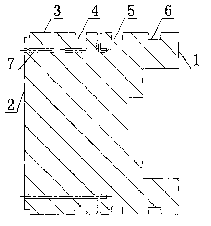
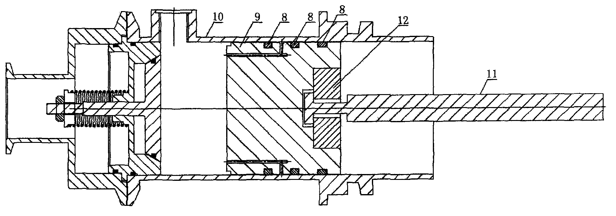
[0013] As shown in Fig. 1, an automatic partial pressure lubrication piston of a filling device includes a cylindrical piston body 1, the front end of the piston body 1 is a pressure bearing surface 2 in contact with the filling material, and the side The wall is an annular outer wall 3 that slides and fits with the inner wall of the barrel 10. The annular outer wall 3 is provided with at least two sealing ring installation grooves, and a sealing ring is arranged in the sealing ring installation grooves. The rear end of the piston body 1 is the connecting end of the piston rod 11. The piston body 1 is provided with a guide flow hole 7 leading from the pressure bearing surface 2 of the piston body 1 to the annular outer wall 3 of the piston body 1, and the outlet of the guide flow hole 7 on the annular outer wall 3 of the piston body 1 is located at two Between adjace...


PUM


Abstract

The invention discloses an automatic partial pressure lubrication piston for a filling device. The automatic partial pressure lubrication piston comprises a cylindrical piston body, wherein the front end surface of the piston body is a piston pressure-bearing surface which is contacted with a filling material; the side wall of the piston body is an annular outer wall which is connected with the inner wall of a charging barrel in a sliding fit mode; at least two sealing ring mounting grooves are formed on the annular outer wall; a sealing ring is arranged in each of the sealing ring mounting grooves; the rear end of the piston body is a piston rod connecting end; a diversion through hole from the pressure-bearing surface of the piston body to the annular outer wall of the piston body is formed on the piston body; and an outlet of the diversion through hole on the annular outer wall of the piston body is positioned between the two adjacent sealing ring mounting grooves. When the automatic partial pressure lubrication piston works, a pasty body of the charging barrel enters a gap between two sealing rings by the diversion hole; and pressure of the pasty body is distributed to the later sealing ring, so that two sealing rings commonly bear the pressure of the pasty body; and therefore, the condition that the previous sealing ring bears the total pressure of the previous pasty body is effectively changed; and because of the lubrication function of the pasty body, the piston is rotated freely, so that the service life of the device is prolonged.

Description

technical field [0001] The invention relates to a piston, in particular to a piston of a filling device used for filling cosmetics, food solutions, materials or pastes. Background technique [0002] In the prior art, the piston filling device used in the food and cosmetic industries usually includes a barrel, a piston, a piston rod and a piston driving device. The piston is arranged in the barrel, and the side wall of the piston is provided with at least two sealing rings. There is a sealing ring (piston ring) in the sealing ring installation groove. The side wall of the piston slides and seals with the inner wall of the barrel through the above sealing ring. The front end surface of the piston is the pressure bearing surface in contact with the filling material. It is fixedly connected to the rear end of the piston, and the piston rod is connected with the piston driving device. When working, the piston driving device drives the piston to reciprocate in the barrel, so as t...

Claims


Application Information

Patent Timeline
Patent Type & Authority Applications(China)
IPC IPC(8): B65B37/06
Inventor 张朝群
Owner 广州市美驰化妆品有限公司
Learn More