Bidirectional biomass gasification furnace

A gasifier and biomass technology, which is applied in the field of small household biomass two-way gasifiers, can solve the problems of complicated operation, difficult control, and harm to the health of users' families.

Inactive Publication Date: 2012-11-28
ZHANGJIAJIE INST OF AERONAUTICAL ENG
View PDF0 Cites 3 Cited by
  • Summary
  • Abstract
  • Description
  • Claims
  • Application Information

AI Technical Summary

Problems solved by technology

But no matter which form, the gasification direction is one-way, and has the following disadvantages: (1) The fire takes a long time, there is thick smoke during the fire stage, and the indoor pollution gas is unpleasant, which will harm the health of users and family members; (2) The operation is complicated and difficult (3) Installation and maintenance are more complicated, and after-sales service is difficult to achieve; (4) Water sealing is used, requiring users to add water to the sealed water tank from time to time, which increases the labor intensity of users; (5) Material barrel and furnace body The connection is integrated, and the material in the barrel is not smoothly discharged, so it is inconvenient to use and maintain

Method used


Image

  • Bidirectional biomass gasification furnace
  • Bidirectional biomass gasification furnace
  • Bidirectional biomass gasification furnace

Examples


Embodiment 1

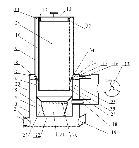
[0018] Such as figure 1 As shown, the two-way gasification furnace is composed of two parts: a two-way gasification chamber 23 and a barrel of rotating material 24. The hanging liner 4 is suspended on the outer casing 3 of the two-way gasification chamber 23, and a seal is formed between the outer casing 3 and the hanging inner bag 4. The gas chamber 25. There is an upper gas port 6 on the top of the suspension liner 4, and a lower gas port 21 at the bottom. The inner side of the lower part of the suspension liner 4 and the double-cone gas ring 5 form a fully enclosed air guide chamber 26, the air guide chamber 26 is connected to the blower 17 through the lower air guide pipe 18, and the middle part of the double-cone gas ring 5 has an oxygen supply hole 20, The bottom of the shell 3 of the two-way gasification chamber 23, that is, the bottom of the gas chamber 25, has an ash outlet 2 and an air outlet 19, the ash outlet 2 has an ash outlet cover 1, and the gas outlet 19 has ...

Embodiment 2

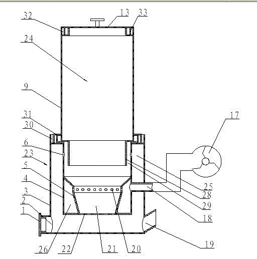
[0020] Such as figure 2 As shown, the difference between Embodiment 2 and Embodiment 1 lies in the shape and structure of the rotating barrel 24 , the sealing method of the joint between the rotating barrel 24 and the casing 3 , and the sealing method of the top of the rotating barrel 24 . The top of the casing 3 is provided with a lower water seal groove 30, and the side of the rotary bucket 24 is provided with a lower water seal ring 31, which is fastened in the lower water seal groove 30; the rotary bucket 24 in this embodiment does not divide the material The lower part of the barrel shell and the barrel liner is stepped. After installation, the length of the lower end exceeds the upper gas port 6, and forms a sandwich layer 28 with the inner wall of the hanging liner 4; the upper end of the rotating barrel 24 is provided with an upper water seal The groove 32 and the feeding cover 13 have a downward material cover water sealing ring 33 , and the material cover water seal...

Embodiment 3

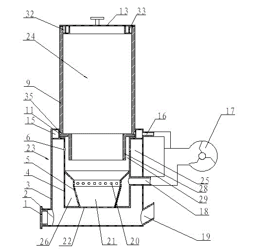
[0022] Such as image 3 As shown, the difference between Embodiment 3 and Embodiment 2 lies in the sealing method of the joint between the rotary cylinder 24 and the casing 3 . The top of the shell 3 is provided with a barrel air seal chamber 15, and the side of the rotating barrel 24 is provided with an annular barrel air seal groove 35, and the barrel air seal chamber 15 communicates with the barrel air seal groove 35 through the air seal hole 11, and passes through The upper air duct 16 communicates with the blower. Others are with embodiment 2.


PUM


Abstract

The invention discloses a bidirectional gasification furnace, wherein a suspension inner container is arranged in the shell of the bidirectional gasification furnace, a gas ring is arranged in the suspension inner container, a closed combustion chamber is formed between the shell and the suspension inner container, an upper gas port is formed in the upper side part of the suspension inner container, a lower gas port is formed in the bottom of the suspension inner container, and a totally-enclosed gas guide chamber is formed between the inner side of the lower part of the suspension inner container and the gas ring, and is connected with a blower through a lower gas guide pipe; and the middle of the gas ring is provided with an oxygen supply hole, and the bottom of the combustion chamber is provided with an ash outlet and a gas outlet. After the bidirectional gasification furnace is fully filled with biomass and the oxygen supply hole of the double-conical gas ring is ignited, because the oxygen supply hole obtains a great quantity of oxygen from the blower, the biomass is quickly burnt under the anaerobic condition, and a great quantity of heat, carbon dioxide and carbon monoxide flows are produced. Two gas ports are formed in the suspension inner container, the hot flows flow along an upper direction and a lower direction, so the bidirectional gasification effect is realized.

Description

technical field [0001] The invention relates to a biomass stove, in particular to a small household biomass two-way gasifier based on the biomass gasification technology. Background technique [0002] At present, there are two types of biomass stoves produced by gasification combustion technology in China: (1) updraft type, that is, the direction of biomass movement and gas movement are reversed; ( 2) Downdraft type, that is, the direction of biomass movement and gas movement are in the same direction. But no matter which form, the gasification direction is one-way, and has the following disadvantages: (1) The fire takes a long time, there is thick smoke during the fire stage, and the indoor pollution gas is unpleasant, which will harm the health of users and family members; (2) The operation is complicated and difficult (3) Installation and maintenance are more complicated, and after-sales service is difficult to achieve; (4) Water sealing is used, requiring users to add w...

Claims


Application Information

Patent Timeline
Patent Type & Authority Applications(China)
IPC IPC(8): C10J3/20C10J3/26C10J3/30
Inventor 高红旺郭紫贵熊隆友刘让贤余益志陈志强
Owner ZHANGJIAJIE INST OF AERONAUTICAL ENG
Why Eureka
Try Eureka