Reduction gear for impeller type washing machine

A deceleration clutch and pulsator washing machine technology, which is applied to other washing machines, washing devices, textiles and papermaking, etc., can solve the problems of high cost, inconvenient assembly, and gaps, and achieve low cost, convenient assembly, and good washing effect Effect

Active Publication Date: 2012-11-28
NINGGUO JULONG IND
View PDF4 Cites 9 Cited by
  • Summary
  • Abstract
  • Description
  • Claims
  • Application Information

AI Technical Summary

Problems solved by technology

[0002] The double-output washing machine with power drive has good washing effect. The deceleration clutch of the washing machine matched with it has two outputs, the output shaft and the output shaft sleeve. The shaft sleeve and the wheel train transmit power through the spline connection. The spline connection has gaps. In the dehydration state, it is easy to generate noise. If you use other methods to connect, not only the cost is high, but also the assembly is inconvenient.

Method used


Image

  • Reduction gear for impeller type washing machine

Examples


Embodiment Construction

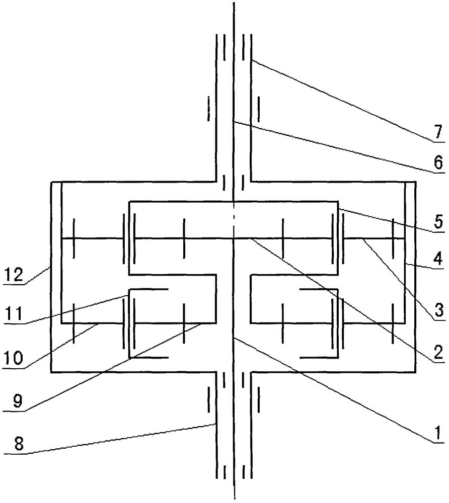
[0016] Combine figure 1 , Is a schematic diagram of the principle structure of an embodiment of a pulsator washing machine deceleration clutch of the present invention. The pulsator washing machine deceleration clutch is mainly composed of an input shaft 1, an output shaft 6, an output sleeve 7, an input sleeve 8 and a brake wheel 12. , The input shaft 1 is installed in the input shaft sleeve 8, the output shaft 6 is installed in the output shaft sleeve 7, the input shaft sleeve 8 is fixedly connected to the lower end of the brake wheel 12, and the lower end of the output shaft sleeve 7 is installed on the brake wheel 12 Inside, the brake wheel 12 is equipped with a double set of planets consisting of input shaft gear 2, upper planetary gear 3, internal gear 4, upper planet carrier 5, center wheel 9, lower planetary gear 10 and lower planet carrier 11. Gear mechanism, the input shaft 1 is connected with the input shaft gear 2, the upper planetary gear 3 is installed on the uppe...


PUM


Abstract

The invention relates to the technical field of impeller type washing machines, in particular to a reduction gear for an impeller type washing machine and overcomes the defects of high cost and inconvenience in assembly in the prior art. The reduction gear mainly comprises an input shaft, an output shaft, an output shaft sleeve, an input shaft sleeve and a brake wheel; the output shaft is arranged in the output shaft sleeve; the lower end of the output shaft sleeve is arranged in the brake wheel; double planetary gear mechanisms consisting of input shaft gears, upper planetary gears, inner gears, upper planetary carriers, central wheels, lower planetary gears and lower planetary carriers are arranged in the brake wheel; the brake wheel is fixedly connected with the output shaft sleeve and the inner gears respectively; the lower planetary gears are arranged on the floating lower planetary carriers; and the rotation directions of the output shaft and the output shaft sleeve are opposite to each other, and the rotation speed can be automatically adjusted according to the load magnitude. By adopting the technical scheme, the reduction gear is low in cost and convenient to assemble; a good washing effect can be achieved; double-direction water flow is formed; and clothes are not damaged.

Description

Technical field [0001] The technical solution of the present invention relates to the technical field of pulsator washing machines, in particular to a deceleration clutch of pulsator washing machines. Background technique [0002] The dual-output washing machine with power drive has a good washing effect. The deceleration clutch of the washing machine matched with it has two outputs: the output shaft and the output sleeve. The shaft sleeve and the gear train transmit power through a spline connection. The spline connection has a gap. In the dehydration state, it is easy to generate noise. If it is connected by other methods, it will not only cost much but also inconvenient assembly. Summary of the invention [0003] The purpose of the present invention is to invent a decelerating clutch for a pulsator washing machine to overcome the existing defects, low cost, and convenient assembly. [0004] According to the above objective, the technical solution of the present invention is: a p...

Claims


Application Information

Patent Timeline
Patent Type & Authority Applications(China)
IPC IPC(8): D06F37/30
Inventor 刘翔杨劲松
Owner NINGGUO JULONG IND
Why Eureka
Try Eureka