Construction method of underground continuous walls

An underground diaphragm wall and construction method technology, applied in sheet pile wall, foundation structure engineering, construction, etc., can solve the problem that the verticality of the groove is difficult to control the flatness of the groove wall, the construction efficiency of the punching pile driver is low, and the hydraulic grab Weak rock capacity and other problems, to achieve the effect of reducing the risk of hole collapse, reducing the cost of mud treatment, and reducing the cost of engineering

Inactive Publication Date: 2012-11-28
CHINA RAILWAY 12TH BUREAU GROUP 7TH CORPORATION LIMITED
View PDF6 Cites 34 Cited by
  • Summary
  • Abstract
  • Description
  • Claims
  • Application Information

AI Technical Summary

Problems solved by technology

However, with this method, it is difficult to control the verticality of the groove and the flatness of the groove walls on both sides, and due to the weak ability of the hydraulic grab to enter the rock,

Method used


Image

  • Construction method of underground continuous walls
  • Construction method of underground continuous walls
  • Construction method of underground continuous walls

Examples


Embodiment

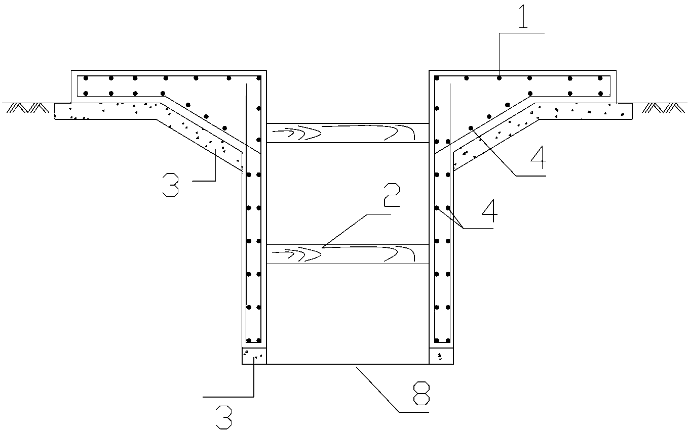
[0029] A specific application of the construction method of the underground diaphragm wall of the present invention in the construction of a certain subway station. The original construction strata of the subway station from top to bottom are respectively: clay layer, gravel layer, pebble layer, and strongly weathered argillaceous siltstone Hezhong weathered argillaceous siltstone; the planned design thickness of the underground diaphragm wall of this station after construction is 800mm, and it is divided into 74 sections in the length direction, with a single section length L of 6m and an average wall depth of 21m.

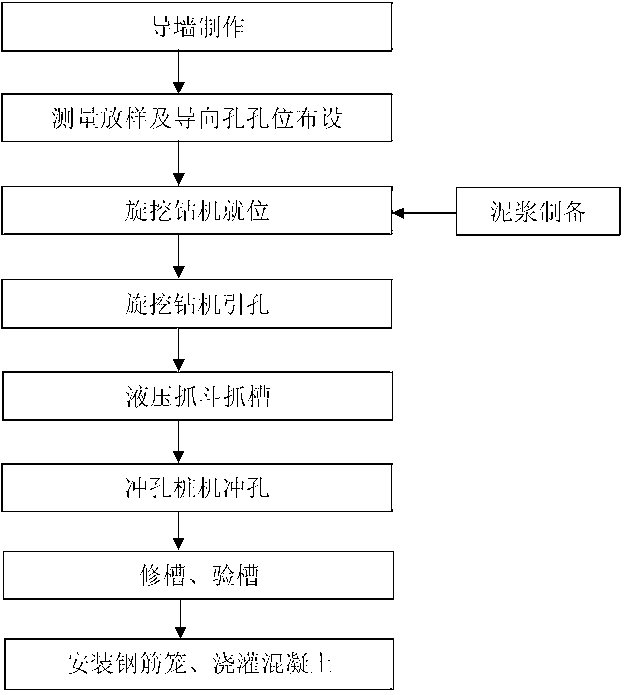
[0030] The construction method flow process of present embodiment underground diaphragm wall is as follows figure 2 As shown, it specifically includes the following steps:

[0031] (1) Fabrication of the guide wall: Excavators are used to excavate the foundation groove of the guide wall, and manual cleaning, tamping and leveling are used. Such as figure 1 As s...


PUM


Abstract

The invention relates to a construction method of underground continuous walls. The construction method comprises the following specific steps: guiding hole by utilizing a rotary drill to form a hole guiding free face, and then adopting a method combining a hydraulic grab bucket and a punching pile machine for punching to carry out grooving construction, so that the verticality of a groove and the flatness of the groove wall are guaranteed, and the grooving construction requirement for different rock-stratum strengths can be met. The construction method has the advantages that the construction is simple and convenient, the operation is easy and the cost is saved and the like.

Description

technical field [0001] The invention belongs to the construction field of an underground diaphragm wall, and in particular relates to a construction method for forming grooves in an underground diaphragm wall. Background technique [0002] At present, the method of combining hydraulic grabs and punching pile machines is often used in the construction process of underground diaphragm wall grooves. Mainly, after the guide wall is completed, the hydraulic grabs are used to construct the grooves first. If the grabs cannot When continuing to grab the groove, use a punching pile driver to punch the groove to the design depth. However, with this method, it is difficult to control the verticality of the groove and the flatness of the groove walls on both sides, and due to the weak ability of the hydraulic grab to enter the rock, it is often necessary to add a large number of punching pile machines to cooperate with the construction, and the construction efficiency of the punching pi...

Claims


Application Information

Patent Timeline
IPC IPC(8): E02D5/18
Inventor 李仁义陈志杜湘豪杜晨
Owner CHINA RAILWAY 12TH BUREAU GROUP 7TH CORPORATION LIMITED
Why Eureka
Try Eureka