
Stop valve and concrete conveying system

A globe valve and conveying pipe technology, applied in the field of fluid material conveying system, globe valve and concrete conveying system, can solve the problems of high processing cost, high assembly cost, complicated structure of globe valve, increased assembly workload, etc. Low cost, stable and reliable work performance, reducing the effect of finishing surfaces

Active Publication Date: 2014-07-16
ZOOMLION HEAVY IND CO LTD
View PDF10 Cites 0 Cited by
  • Summary
  • Abstract
  • Description
  • Claims
  • Application Information

AI Technical Summary

Problems solved by technology

It can be seen that the structure of the globe valve in the prior art is quite complicated, and the contact surfaces between the various components need to be finished, which not only significantly increases the assembly workload, but also leads to higher processing and assembly costs.

Method used


Image

  • Stop valve and concrete conveying system
  • Stop valve and concrete conveying system
  • Stop valve and concrete conveying system

Examples


Embodiment Construction

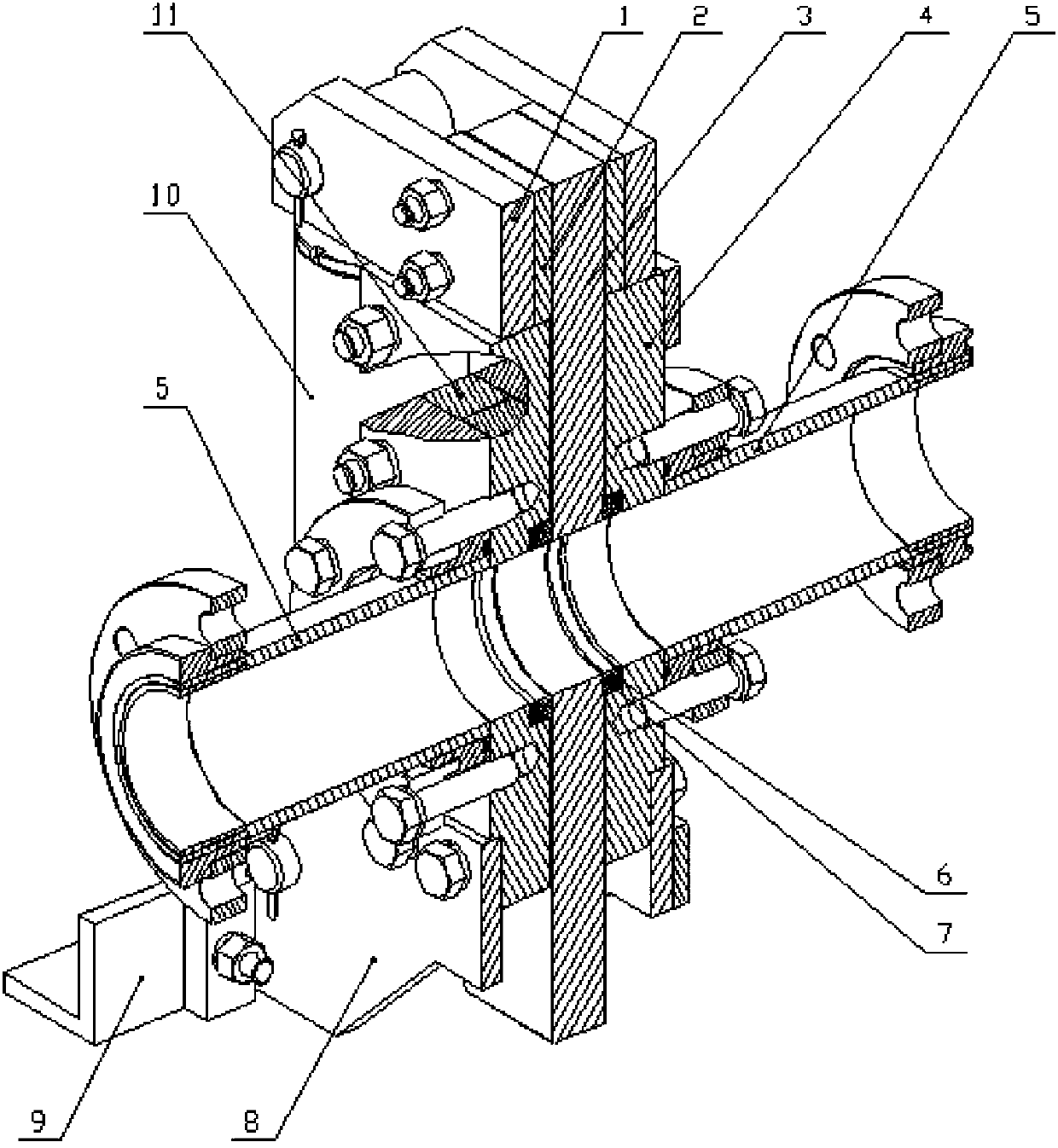
[0072] The specific embodiments of the present invention will be described in detail below in conjunction with the accompanying drawings. It should be understood that the specific embodiments described here are only used to illustrate and explain the present invention, and the protection scope of the present invention is not limited to the following specific embodiments. .

[0073] First of all, in the description of specific embodiments below, some orientation words used for ease of understanding, such as up, down, left, right, etc., are described according to the orientation shown in the drawings, but these orientation words are not Should constitute a limitation to the protection scope of the present invention, because the installation position of shut-off valve is various in practice, for example figure 1 The cut-off valve shown can be hoisted with the base facing up according to the requirements of the installation space during the actual installation process, so some ori...


PUM


Abstract

The invention relates to a stop valve which comprises a valve seat (3), a valve body (2) and an extension driving device, wherein a valve body conveying hole (19) is formed on the valve body (2); a valve body accommodating slot (26) and first and second through holes (29, 30) are formed on the valve seat (3); and the valve body is hinged on the valve seat and is located in the valve body accommodating slot, both ends of the expansion driving device are respectively hinged on the valve body and the valve seat so as to drive the valve body to rotate such that both ends of the valve body conveying hole are aligned and connected with one corresponding ends of the first and second through holes or the valve body seals the first and second through holes. In addition, the invention also provides a concrete conveying system comprising the stop valve. The stop valve provided by the invention has simple structure and is reliable in working, the valve seat and the valve body can both be overall structures, the overall rigidity is good, the quantity of members is relatively small, the assembly operation is simplified, the valve body rotates in relative to the valve seat to realize conduction or stopping, and the stop valve works relatively reliably.

Description

technical field [0001] The invention relates to an on-off control valve used on a fluid material delivery pipeline, in particular to a cut-off valve, which is mainly suitable for delivery systems of fluid materials such as concrete and mud. Furthermore, the present invention also relates to a concrete conveying system comprising the shut-off valve. Background technique [0002] Generally speaking, the shut-off valve is installed on the delivery pipeline of the fluid material, and the fluid material delivery pipeline is turned on or off by operating the shut-off valve. There are various forms of stop valves. A typical stop valve refers to a valve whose closing member moves along the centerline of the valve seat, but it is not limited to this. The structure forms of stop valves used in various fields are diverse. The stop valve described in the present invention The meaning of valves in a broad sense is adopted. For example, the stop valve used in the pipeline of viscous flui...

Claims


Application Information

Patent Timeline
Patent Type & Authority Patents(China)
IPC IPC(8): F16K3/02F16K3/30F16K27/04F16N1/00
Inventor 樊兴胜
Owner ZOOMLION HEAVY IND CO LTD
Features
  • Generate Ideas
  • Intellectual Property
  • Life Sciences
  • Materials
  • Tech Scout
  • Unparalleled Data Quality
  • Higher Quality Content
  • 60% Fewer Hallucinations
Learn More