Eureka AIR delivers breakthrough ideas for toughest innovation challenges, trusted by R&D personnel around the world.

Backlight module

A backlight module and backplane technology, which is applied to electric light sources, light source fixing, lighting devices, etc., can solve problems such as cracks, lack of good fixing effect on light guide plates, and melting

Inactive Publication Date: 2012-11-28
CHI LIN OPTOELECTRONICS CO LTD
View PDF8 Cites 6 Cited by
  • Summary
  • Abstract
  • Description
  • Claims
  • Application Information

AI Technical Summary

Problems solved by technology

[0007] The technical problem to be solved by the present invention is: the processing hours and processing cost of the existing backlight module are high; or the light guide plate does not have a good fixing effect, there will be a problem of melting after being heated, or it will break when it is subjected to mechanical impact

Method used


Image

  • Backlight module
  • Backlight module
  • Backlight module

Examples


Embodiment Construction

[0080] Figure 2A It shows a three-dimensional exploded view of the first embodiment of the backlight module of the present invention; Figure 2B It shows a combined rear top view of the first embodiment of the backlight module of the present invention; Figure 2C A rear sectional view showing the assembly of the first embodiment of the backlight module of the present invention is shown. with reference Figure 2A to Figure 2C , the backlight module 2 includes a backplane 21 , a light guide plate 22 , at least one light source 23 , an optical film 24 and a plastic frame 25 .

[0081] In this embodiment, the backboard 21 includes a bottom board 211 and four sidewalls 212 , and the sidewalls 212 are substantially vertically connected to the bottom board 211 so that the backboard 21 forms an accommodating space. The light guide plate 22 is disposed on the bottom plate 211 of the back plate 21 for guiding the light from the at least one light source 23 to the light emitting surf...


PUM


Abstract

The present invention relates to a backlight module, comprising a back plate, a light guide plate, at least one light source, an optical film, and a glue frame; wherein, the light guide plate is arranged on the back plate, and has at least one light-in surface and one light-out surface; the at least one light source faces to the at least one light-in surface; the optical film is arranged at the light-out surface of the light guide plate; the glue frame is arranged at a periphery of the light guide plate, and has a rib part and a plurality of column parts, the rib part is arranged at a relative position over a periphery of the light-out surface, the column parts are connected with the rib part and arranged between the rib part and the back plate, so that an end face of the column part is lower than the light-out surface. Therefore, the backlight module can reduce processing time and part cost, prevent the problem of fracture and melt of the light guide plate after being heated, and fix the optical film and the light guide plate.

Description

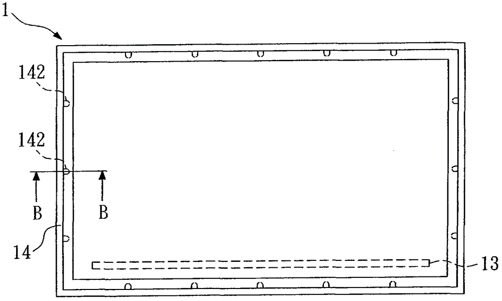
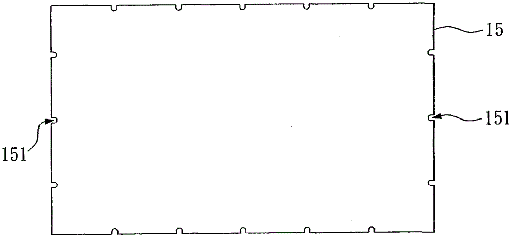
technical field [0001] The invention relates to a backlight module, in particular to a backlight module which has a plastic frame and the end faces of a plurality of pillars of the plastic frame are lower than the light-emitting surface. Background technique [0002] Figure 1A A top view showing the existing backlight module disclosed in Taiwan Patent No. I287664; Figure 1B A cross-sectional view showing a conventional backlight module disclosed in Taiwan Patent No. I287664; Figure 1C A top view of an optical film of a conventional backlight module disclosed in Taiwan Patent No. I287664 is shown. with reference Figure 1A to Figure 1C , the existing backlight module 1 includes a backplane 11 , a light guide plate 12 , a light source 13 , a plastic frame 14 and a multilayer optical film 15 . The light guide plate 12 is disposed on the back plate 11 and has a light emitting surface 121 . The light source 13 is close to a side wall of the light guide plate 12 . [0003]...

Claims


Application Information

Patent Timeline
IPC IPC(8): F21S8/00F21V13/00F21V17/00
Inventor 钟丰建
Owner CHI LIN OPTOELECTRONICS CO LTD
Why Eureka
Eureka Blog
Learn More